BOARD CUSTOMISATION
Overview
The 3D Viewer provides a number of options allowing you to customize both the appearance and view of the board. These are board level commands and quite distinct from customization of models/footprints which is discussed in detail in a subsequent topic.
Dimension Configuration
Clearly the size of the board is determined by the board edge in the ARES Layout package. You can however, configure board thickness, feature thickness and height clearance from the Dimensions command on the Settings menu.
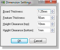
Dimension settings in the 3D Viewer
The board thickness defaults to 1.25mm but can be adjusted within the range of 0.1mm to 10mm. The feature thickness is the amount by which the tracks and silkscreen graphics are extruded from the board (if you zoom in closely you can see this). By default this is set to be 50um – adjusting this to say, 500um, would present a far more extreme view of the board.
The height clearance at the top and bottom represent the dimensions of the container for the PCB and – together with the heights bounds icon – allow you to check whether your PCB will fit in the container.

Height icon
Colour Configuration
In addition to configuration of general board dimensions we can control the base colours for the board. This is handled via the Colours command on the Settings menu.
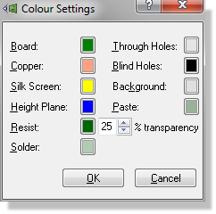
Colour settings
The options are all fairly self-explanatory and, while the defaults are perfectly adequate, it is quite simple (and surprisingly effective) to adjust the values to match either the physical board or your personal preferences. For example, the board below is a pretty realistic representation of Microchip Technology’s™ PICDEM 2+ Evaluation Board.
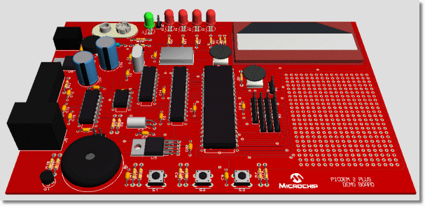
Microchip Technology’s™ PICDEM 2+ Evaluation Board