HEIGHT PLANE CLEARANCE
Overview
This feature allows you to define a bounding box (representing the container for the board) of specified dimensions. When enabled. the box will appear in a semi-transparent colour around the board allowing you to quickly determine which objects protrude from the container.
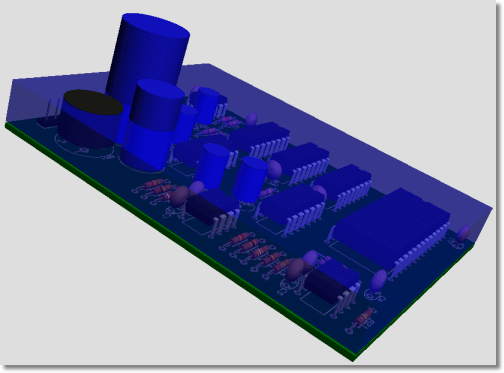
Height clearance box shows any components that will be too tall
To specify the dimensions of the bounding box
- From the 3D Viewer select the Settings Menu and then the Dimensions command.
- Specify the required dimensions for Height Clearance (Top) and Height Clearance (Bottom).
- Select the OK button to exit the dialogue form.
The height of the components may not be exact to the 'real world device'. Packages with assigned STEP models should be checked by the user before exporting the board for MCAD production
To enable viewing of the bounding box
- Select the 3D Bounds icon (at the right of the
bottom toolbar in the 3D Viewer)
OR - Select the Height Bounds command from the View menu in the 3D Viewer.
This command can be toggled to enable / disable the height bounding box
To change the colour of the bounding box
- From the 3D Viewer select the Settings Menu and then the Colours command.
- Click on the Height Plane checkbox and change the colour as desired.
- Select the OK button to exit the dialogue form.