PATTERN GENERATOR MODEL
Overview
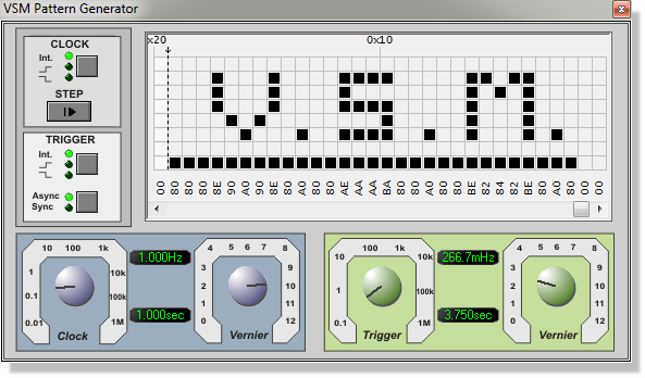
The VSM Pattern Generator is the digital equivalent of the analogue Signal Generator and is provided as standard with all professional versions of the Proteus simulation software.
The VSM Pattern Generator allows for an 8-bit pattern of up to 1K bytes and supports the following main features:
- Will run in either graph based or interactive mode.
- Internal and External Clocking and Trigger modes.
- Vernier adjustment for both clock and trigger dials.
- Hexadecimal or Decimal grid display modes.
- Direct entry of specific values for greater accuracy.
- Loading and saving of pattern scripts.
- Manual specification of pattern period length.
- Single Step control allows you to advance the pattern incrementally.
- Tooltip Display allows you to see exactly where you are on the grid.
- Ability to externally hold the pattern in it’s current state.
- Block Editing commands on the grid for easier pattern configuration.
Using the Pattern Generator
To output a pattern in an interactive simulation
- Pick the PattGen by selecting the Meter icon in
ISIS and then selecting the Pattern Generator from the Object Selector.

- Initialise an interactive simulation by pressing the pause button on the Animation Control Panel. The Pattern Generator window should appear.
- Specify the pattern that you want to output by left clicking on grid squares to toggle their logic states.
- Decide whether you are clocking internally or externally
and set the clock mode button to reflect your choice.
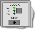
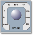
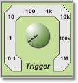
- If you are clocking internally adjust the clock
dials to specify the desired clock frequency.
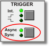
- Decide whether you are triggering internally or
externally and use the trigger buttons to set the mode accordingly.
If you are triggering externally you need to think about whether you
want to trigger asynchronously or synchronously with the clock.
- If you are triggering internally adjust the trigger
dials to specify the desired trigger frequency.
- Press the play button on the Animation Control Panel to output the pattern.
- To advance the pattern by a single clock cycle press the 'Step' button on the Animation Control Panel and then the step button to the left of the grid.
See Trigger Modes for details of the different trigger modes available with the Pattern Generator.
See Additional Functionality for more information on configuring and using the Pattern Generator.
To output a pattern in a graph based simulation
- Set up the circuit in the normal way.
- Insert probes on the schematic at points of interest and add those probes to the graph.
- Right click and then left click on the Pattern
Generator on the schematic to get the Edit Component dialogue form.
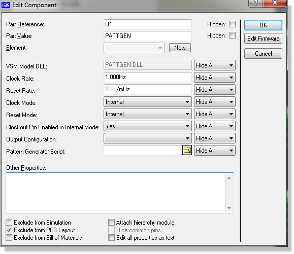
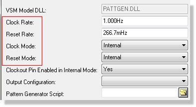
- Configure the Trigger and Clock options.
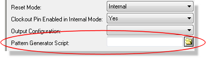
- Load the desired pattern file into the Pattern
Generator Script field.
- Exit the Pattern Generator Dialogue Form and hit the space bar to run the simulation
The Pattern Generator Component Pins
Data Output Pins (Tri-State Output)
The Pattern Generator can output either on a bus and/or on individual pins.
Clockout Pin (Output)
When the Pattern Generator is clocking internally you can configure this pin to mirror the internal clock pulses. This is set as a property and can be changed via the Edit Component dialogue form. By default this option is disabled as it incurs a performance hit, particularly for high frequency clocks.
Cascade Pin (Output)
The Cascade Pin is driven high when the first bit of the pattern is being driven and remains high until the next bit is driven (one clock cycle later). This means it is high for the first clock cycle on starting the simulation and again for the first clock cycle subsequent to a reset.
Trigger Pin (Input)
This input pin is used to feed an external trigger pulse into the Pattern Generator. There are four external trigger modes which are discussed in detail here.
Clock-In Pin (Input)
This input pin is used to apply external timing to the Pattern Generator. There are two external clocking modes which are discussed in greater depth here
Hold Pin (Input)
This pin, when driven high can be used to pause the Pattern Generator. The pattern will remain at the point it was at until the hold pin is released. For internal clocking and/or trigger the timing will resume relative to the point at which is was paused. For example, on a 1Hz internal clock, if the pattern is paused at time 3.6 seconds and resumed at 5.2 seconds then the next falling clock edge will be at 5.6 seconds.
Output Enable Pin (Input)
This pin must be driven high in order to enable the output pins. If this pin is not high then the Pattern Generator, while still running the specified pattern, will not drive the pattern onto the output pins.
Clocking Modes
Internal Clocking
Internal clocking is negative edge. That is, the clock pulse will be low-high-low per clock cycle.
Internal clocking can be specified either prior to simulation via the Edit Component dialogue form for the Pattern Generator or during a pause in the simulation via the clock mode button.
The Clockout pin, when enabled, mirrors the internal clock. By default, this pin is disabled as it will cause some performance loss (particularly with high frequency clocks) but it can be enabled via the Edit Component dialogue form for the Pattern Generator.
External Clocking
There are two external clocking modes – negative edge (low-high-low) and positive edge (high-low-high).
To clock externally wire the clock pulse to the Clockin pin and select one of the two external clocking modes.
As with Internal clocking you can change the external clocking mode either by editing the component prior to simulation or via the clock mode button during a pause in the simulation
Trigger Modes
Internal Trigger
The Internal Trigger Mode in the Pattern Generator triggers the pattern at specified intervals. If the clocking is internal the clock pulse is reset at this point. This behaviour is shown graphically below.
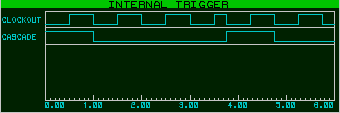
We are clocking internally at 1Hz and the internal trigger time is set to 3.75sec. The Cascade pin is high while the first bit of the pattern is being driven on the pins and low at all other times.
Note that at trigger time the internal clock is asynchronously reset. The first bit of the pattern is driven onto the output pins (as evidenced by the Cascade Pin being driven high).
External Asynchronous Positive Edge Trigger
The trigger is specified via a positive edge transition on the Trigger Pin. The Trigger actions immediately and the next clock edge will be a low-high transition at time bitclock/2 subsequent to the time of the reset as shown below.
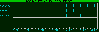
We are clocking internally at 1Hz and the trigger pin goes high at time 3.75sec. Immediately on the positive edge of the trigger pin the clock is reset and the first bit of the pattern is driven onto the pins.
External Synchronous Positive Edge Trigger
The trigger is specified via a positive edge transition on the Trigger Pin. The trigger is latched and will action synchronously with the next falling clock edge as shown below.
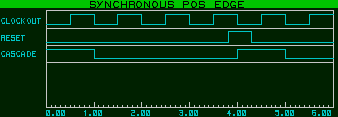
We are clocking internally at 1Hz. Note that the clock is unaffected by the trigger and that the trigger actions on the falling clock edge subsequent to the positive edge pulse.
External Asynchronous Negative Edge Trigger
The trigger is specified via a negative edge transition on the Trigger Pin. The trigger actions immediately and the first bit of the pattern is driven onto the output pins.
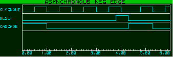
We are clocking internally at 1Hz. We can see that clock resets on the negative edge of the trigger pulse and that the first bit of the pattern is driven at that time.
External Synchronous Negative Edge Trigger
The trigger is specified via a negative edge transition on the Trigger Pin. The trigger is latched and actions synchronously with the next falling edge clock transition as shown below.
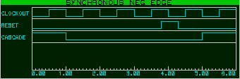
We are clocking internally at 1Hz. Note that the trigger takes place on the falling edge of the trigger pulse and that the pattern does not reset until the falling edge of the clock pulse subsequent to the trigger action.
External Hold
If you want to hold the pattern for a period of time you can do so by arranging for the hold pin to be high during the period in which you want to pause. Releasing the hold pin will restart the pattern synchronously if you are using an internal clock. That is, should the hold pin go high halfway through a clock cycle, then when you release the hold pin the next bit will be driven onto the output pins half a clock cycle later.
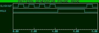
When the hold pin goes high the internal clock is paused. On release of the hold pin the clock resumes relative to the point in the clock cycle at which it was paused.
Additional Functionality
Loading and saving a pattern script.
Pattern Scripts can be loaded or saved by right clicking over the grid and selecting the relevant option from the popup menu. This is particularly useful if you want to use a particular pattern in several designs.
The pattern scripts are plain text and are simply a comma-separated list of bytes where each byte value represents a column on the grid. Any line beginning with a semi-colon is taken to be a comment line and is ignored by the parser. By default the byte format is hexadecimal though if you are creating your own script you can enter values is decimal, binary or hexadecimal.
Setting specific values for dials.
You can specify an exact value for both the bit and the trigger frequency by double clicking the mouse on the appropriate dials. This launches a floating edit box into which you can enter the value. By default the value entered is assumed to be a frequency but you can specify a value in seconds or fractions thereof by appending a suitable suffix to the value (sec, ms, etc.). Additionally, should you wish the trigger to be an exact multiple of the bit clock you can append the suffix ‘bits’ to the multiple desired (e.g. 5bits).
To confirm input press the Enter button or to cancel press the Escape key or click elsewhere on the Pattern Generator window.
These values can also be specified prior to simulation via the appropriate properties in the Edit Component dialogue form.
Setting specific values for the pattern grid.
You can specify a specific value for any column on the grid by left clicking the mouse on the text displaying the current value for that column. A floating edit box is launched into which you can enter the desired value. You can specify the value in decimal (e.g. 135), hexadecimal (e.g. 0xA7) or binary (e.g. 0b10110101).
To confirm input press the Enter button or to cancel press the Escape key or click elsewhere on the Pattern Generator window.
For convenience you can set a column via the CTRL+1 keyboard shortcut and clear a column via the CTRL+SHIFT+1 keyboard shortcut with the mouse over the appropriate column.
Specifying the period length of the pattern manually.
You can specify a manual period by left clicking the mouse just above the grid itself at the column you want the pattern to finish on. To deselect the period right click the mouse once in the same area.
Single stepping to advance the pattern.
The step button can be used to advance the simulation in time periods equal to that of the bitclock specified either internally or from an external clock. The simulation will run until the next clock cycle is completed and then suspend again.
Alternating the grid display mode.
The grid display can be switched between hexadecimal and decimal display modes. This can be done either by right clicking on the grid and selecting the desired option from the menu or alternatively by using the CTRL+X (Hexadecimal display) and CTRL+D (Decimal display) shortcut keys.
Specifying Output.
Edit the Schematic part for the Pattern Generator to produce the Edit Component dialogue form. The property at the bottom allows you to configure whether you want to output the pattern on both bus and pins, pins only or bus only.
Tooltip Display.
You can enable a tooltip which will follow the mouse indicating the current row and column information. This can be toggled on and off either via the context mouse on the right mouse button or through the shortcut key CTRL+Q. Note that tooltip mode is disabled during a Block set or clear.
Block Editing.
You can use the Block Set and Block Clear commands to help you quickly configure the grid to the desired pattern. These are accessible via the context menu on the right mouse button or via their shortcut keys (CTRL+S for Block set and CTRL+C for Block clear). Note that the Block Editing commands are disabled when in tooltip mode.