TIMER COUNTER MODEL
Overview
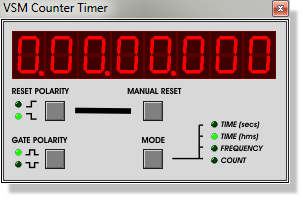
The VSM Counter Timer is a multi-purpose digital instrument which can be used to measure time intervals, signal frequency and pulse counts.
The counter timer supports the following operating modes:
- Timer mode (seconds), resolution 1µs.
- Timer mode (hours, mins, secs), resolution 1ms.
- Frequency meter mode, resolution 1Hz.
- Counter mode - maximum count 99,999,999.
The time, frequency or count value is displayed both on the schematic component and also optionally on the counter timer popup as shown above. You can make the popup appear either by clicking left on the counter timer component or by selecting it from the Debug menu whilst the simulation is running.
Using the Timer Mode
To measure time intervals:
- Select the Multimeter icon, pick the COUNTER TIMER
and place one on the schematic.

- If appropriate, wire the CE (clock enable) pin to a signal that will control when the time display advances. If you don't require a clock enable function you can leave this pin floating.
- If appropriate, wire the RST (reset) pin to a signal that will switch state to reset the timer to zero. If you don't need to reset the timer from within the circuit you can leave this pin floating.
- Point at the Counter Timer and press CTRL - E to
edit its settings.
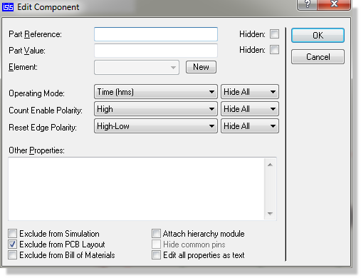
- Select the required timer mode (secs or hms) and
logic polarities for the CE and RST functions.
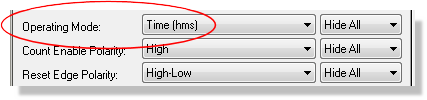
- Start the simulation in the usual way.
The RST pin is edge triggered as opposed to level triggered. If you need to hold the timer at zero, you can use the CE and RST pins in combination.
The Counter Timer popup provides a manual reset button which will reset the timer to zero at any point during the simulation run. This can be especially useful in embedded systems work where you can use the Counter Timer to establish the time taken to execute particular sections of a program.
Using the Frequency Mode
To measure the frequency of a digital signal:
- Select the Multimeter icon, pick the COUNTER TIMER
and place one on the schematic.
- Wire the CLK (clock) pin to the signal you wish to measure. The CE and RST pins are not used in frequency mode.
- Point at the Counter Timer and press Ctrl-E to
edit its settings and then select Frequency Mode
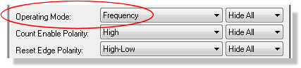
- Close the dialogue and start the simulation in the usual way.
The frequency meter works by counting the number of positive edge transitions occurring in each second of simulation time. Consequently it needs a full second of steady input signal to display a valid reading. Also, if the simulation is not occurring at real time speed (due to heavy CPU load), the frequency meter will take longer in real time to produce a reading.
The counter timer is a purely digital component. To measure the frequency of a low level analogue signal you will need to place an ADC primitive with appropriate logic thresholds in front of the counter timer CLK pin. Also, due to the fact that analogue simulation is approximately 1000 times slower than digital simulation, the Counter Timer is not really suitable for determining the frequency of analogue oscillator circuits operating much above 10kHz. In such cases you should use the virtual oscilloscope (or a graph) to measure the signal period.
Using the Counter Mode
To count digital pulses
- Select the Multimeter icon, pick the COUNTER TIMER
and place one on the schematic, wiring the CLK (clock) pin to the
source signal.
- If appropriate, wire the CE (clock enable) pin to a signal that will control when the count advances. If you don't require a clock enable function you can leave this pin floating.
- If appropriate, wire the RST (reset) pin to a signal that will switch state to reset the count to zero. If you don't need to reset the counter from within the circuit you can leave this pin floating.
- Point at the Counter Timer and press CTRL - E to edit its settings.
- Select Counter Mode) and appropriate logic polarities
for the CE and RST functions.
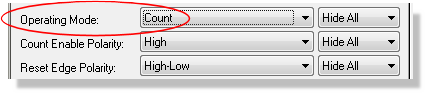
- Start the simulation in the usual way.
The count advances on positive edge transitions of the CLK when CE is active.
The RST pin is edge triggered as opposed to level triggered. If you need to hold the count at zero, you can use the CE and RST pins in combination.
The Counter Timer popup provides a manual reset button which will reset the count to zero at any point during the simulation run.