BUILDING AND USING ESP8266 SERVER
Introduction
Labcenter's support for ESP8266 is primarily provided via the Proteus Playkit hardware. This is a ready made solution with a pre-programmed ESP8266. The following guide explains how to set up an ESP8266 server manually but we strongly recommend that it is only implemented by advanced users.
This document describes the steps for configuring a WeMOS D1 Mini (ESP8266) board as a VFP (Virtual Front Panel) server for use with Proteus IoT Builder for Arduino. A similar procedure will also work for other ESP8266 based modules such as the Node MCU provided that they have a micro USB connector.
A slightly different procedure is needed for the ESP13 shield – please see the additional information at the end of this document.
Note that the ESP8266 is used as an IoT Co-Processor for the Arduino; the user’s application runs on the AVR chip, not the ESP8266. This allows it make full use of the wide range of shields and libraries that are available for the standard Arduino Uno and Mega boards, whilst also having access to the ESP8266 flash based file store (SPIFFS).
The hardware required consists of:
- WeMOS D1 Mini board c/w SIL headers
- Arduino Prototyping Shield c/w mini breadboard
- Connecting wires
- Arduino Uno
The steps to be carried out are as follows:
- Solder the SIL headers to the WeMOS D1 mini
- Program the WeMOS D1 with the Vfp8266 firmware
- Configure the Vfp8266 firmware to connect your WiFi network.
- Wire the WeMOS D1 to the Arduino Prototype Shield
- Attach the Prototype Shield to the Arduino Hardware
Once these steps have been completed, you can upload the appliance firmware and resources from Proteus IoT Builder over the WiFi connection. The ESP8266 will act as an ICSP for the Arduino and also provides a telnet debug channel and FTP access to the file store.
This setup is also summarized in a short movie on our Youtube channel.
Soldering the SIL Headers
The WeMOS D1 mini is supplied as a simple PCB module along with a number of different PCB connectors.

In order to mount it on the mini breadboard, the two SIL connector strips should be soldered to the underside of the D1 module as shown above.
Programming the WeMOS D1 with the VFP8266 Firmware
As supplied, the WeMOS D1 is loaded with the standard DOIT firmware which operates as a serial->TCPIP interface. However, before the module can be used with IoT Builder, this needs to be replaced with the Vfp8266 firmware. Since the re-flashing process requires a connection to the micro-USB slot, this step is most easily performed before the module is mounted on the prototyping shield.
The Vfp8266 binaries can be found within your Proteus installation at
VSM Studio/drivers/Arduino/Vfp8266/firmware/VfpServer.ino.d1_mini.bin
VSM Studio/drivers/Arduino/Vfp8266/firmware/VfpServer.ino.ESP13shield.bin
Different binaries are needed due to differences in the connection of the built in LED.
To upload it to the ESP8266 flash you will need the NodeMCU flasher utility which is available from here:
https://github.com/nodemcu/nodemcu-flasher
You should download the exe file from the Win32/Release or Win64/Release folder according to the version of Windows that you are running.
Connect the WeMOS D1 to a USB port on your PC with a micro-USB cable. If the driver does not exist on your machine you will need to download it from here: http://www.wch.cn/downloads/CH341SER_ZIP.html. Install the driver and the CH340 will also create a new COM port on your machine.
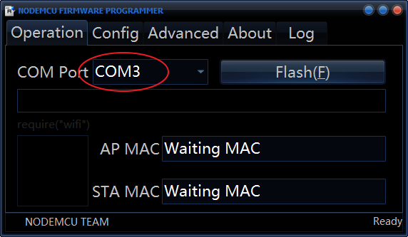
Now run the ESP8266Flasher.exe program. It should find the COM port that the ESP8266 has created and display a screen similar to the one below.
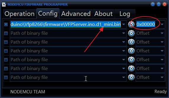
Click Config and modify the settings as shown below. You are telling it to flash the contents of the single VfpServer.ini.xxx.bin file to location 0x00000. Make sure that only one checkbox is ticked.
Go back to the Operation screen and click the Flash button. If all is well then you should see a QR code and a blue progress bar as the new firmware is loaded into the ESP8266.
When this process has completed, press the reset button on the WeMOS D1 (or power cycle it) to reboot and it should then create a unique WiFi Access point with an SSID such as ‘ESP8266_528854’. Also, the LED on the ESP8266 module should start blinking at about 2Hz. This is the end user configuration mechanism and allows a user of your appliance to connect it to their own WiFi network. However, for our purposes here we need it to facilitate programming of the Arduino from within Proteus.
If you cannot connect to the ESP8266_xxxx WIFI then you will need to Erase the flash on Page 0. Please see the trouble shooting section on how to do this.
Configuring the VFP8266 Firmware
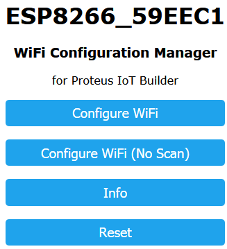
With the ESP8266 successfully re-flashed, you can connect your PC’s WiFi to the temporary AP that it has created. If you then point a web browser to the IP address 192.168.4.1 you should see a screen similar to the one below:
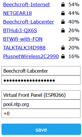
Click Configure WiFi and select your main WiFi network from the list. You will also need to enter the WiFi password if such is required:
If this screen does not show properly the first time, try refreshing page in your browser
The 3 fields at the bottom allow configuration of the appliance name, a time (NTP) server and a time offset in hours. You should set this last value to match your current time zone.
When you are done, click save. The ESP8266 LED should blink for a short while and then become steady. This indicates a successful connection to your WiFi network and you are now ready to wire up the hardware.
Note that if the appliance fails to connect to the configured WiFi network at start up, it will automatically enter the end-user configuration mode. This makes it possible to re-configure the WiFi settings at a new location, or if either the SSID or password for your network is changed.
Wiring the WeMOS D1 Mini to the Arduino Prototype Shield
Disconnect the WeMOS D1 from your PC and insert it into the mini breadboard. Then, use the connecting wires to link it to the Arduino terminals. The connections to be made are as follows:
| WeMOS D1 | Arduino Uno |
GND |
GND |
+5V |
+5V |
RX |
TX |
TX |
RX |
SCK/D5/GPIO14 |
SCK/IO13 |
MOSI/D7/GPIO13 |
MOSI/IO11 |
MISO/D6/GPIO12 |
MISO/IO12 |
D3/GPIO0 |
RST |
When this stage is completed, physical hardware should look something like the version on the left:
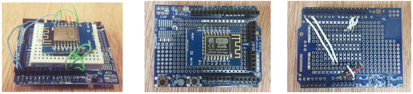
Alternatively, you can dispense with the mini breadboard and make a fully soldered solution as shown centre and right. This will be considerably more robust but you won’t be able to use the WeMOS D1 or the Prototype Shield for anything else.
Attach the Prototype Shield to the Arduino Hardware
The final stage of this assembly process is to plug the Prototyping Shield onto the Arduino Uno.
Firstly you will need to disable the on board USB->Serial interface on the Uno. Otherwise the USB->Serial chip on the WeMOS D1 will not be able to communicate with the ESP8266. This is achieved by connecting a jumper onto its ICSP connector as shown below left:
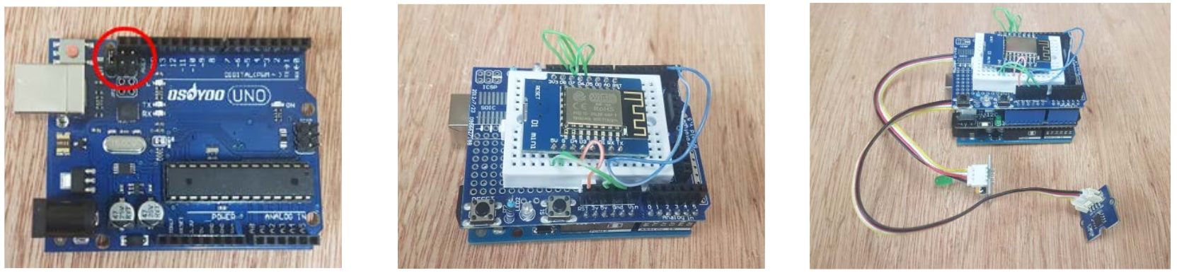
If you are wanting to use additional hardware shields such as the Grove Shield, this needs to sit between the Arduino and the prototyping shield, as shown on the right.
Either way, the completed system can be powered by the micro-USB on the WeMOS D1, the standard USB on the Arduino or the power jack on the Arduino.
Uploading the Appliance Framework Firmware from Proteus IoT Builder
The hardware is now ready to be programmed from Proteus. Whereas the previous steps need to be carried out just the once, this last step can be repeated as many times as you like during the process of developing the appliance firmware. Of course, you can also simulate the appliance within Proteus VSM so, in most circumstances you would expect to deploy to the real hardware only right at the end of the software development process.
For the purposes of this document, we shall make use of an existing sample design. Open a copy of Proteus and then click Open Sample. Enter ‘ESP8266’ into the keywords and open the ‘ESP8266 – Blink an LED’ project.
Make sure that your assembled hardware is powered up and connected to the same WiFi network as your PC. The ESP8266 LED should be on and not blinking.
Click the Visual Designer tab and open Project Settings from the Project menu.
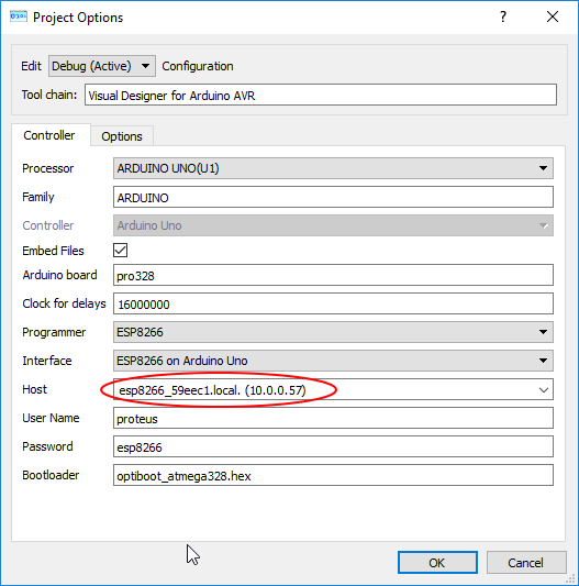
You will be programming the Arduino (AVR) via the ESP8266 module so the Programmer should be set to ESP8266. Assuming your Arduino board is an Uno, then the Interface should be set to ESP8266 on Arduino Uno. Finally you need to specify the host IP address for the ESP8266 board. Fortunately, the Vfp8266 firmware announces itself via MDNS (aka Zeroconf or Bonjour) and so Proteus should be able to discover it automatically, as shown above. Once you’ve made these selections you can click OK.
Then select Build/Upload from the menus or click the Upload icon. Proteus will transfer the resource files to the ESP8266 flash storage via FTP and then it will use a local copy of AVRDUDE to program the AVR firmware via a network serial protocol. The ESP8266 LED will blink rapidly during this second stage.
Assuming that all is well, you should get a status report something like this:
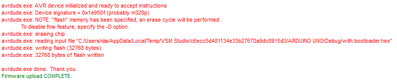
You can then try out the appliance either by pointing a web browser at its IP address, or by using the Proteus IoT Controller mobile app. As with the programming port, the Vfp8266 firmware announces the VFP service via MDNS so that the Proteus Iot Controller App can discover it.
If the programming fails, you should check that all the breadboard wiring is present and correct.
Remote Debugging
As with the VFP implementation for the Arduino Yun Shield, a significantly difficulty can arise whilst developing the AVR firmware in that the AVR’s UART is used by the bridge connection to the co-processor and there is therefore no easy means to view debugging output from the AVR code. What we are saying here is that the normal Arduino technique of
Serial.println(“Some debug info…”);
cannot be used because the Serial port is in use via the Bridge class.
In simulation, this is solved by virtue of the Proteus VSM AVR model having a back-door which allows us to send messages from the AVR code directly to the VSM simulation log. However this is clearly not possible on real hardware.
Instead, the Vfp8266 firmware implements a remote debugging console via telnet. You can connect to this using a standard telnet client such as PuTTy.
https://www.chiark.greenend.org.uk/~sgtatham/putty/
Set up a telnet connection to the ESP8266 using the IP address discovered by Proteus whilst programming
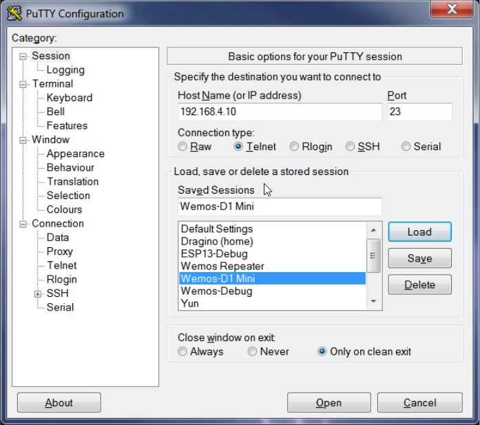
Then, you can click Open to connect to your appliance. The debug terminal shows status messages related to the Vfp8266 firmware including activity related to the web server such as files being sent to the browser. In addition, it will display any messages sent via the debug method of the Server object in the flowchart and/or the Console object in C++ code.
You can also reset the appliance to its default state (end user configuration mode) by entering the command reset at the telnet prompt.
FTP Server
The Vfp8266 firmware operates a basic FTP server on port 21. The username is proteus and the password is esp8266. This is used primarily by Proteus for uploading resources but it can also be used to inspect or modify the contents of the ESP8266 (SPIFFS) filestore.
The FileZilla tool can be used to access the FTP server.
LED Blink Pattern
The Vfp8266 firmware uses the built in blue LED on the WeMOS D1 module to indicate various operating conditions.
| Blink Pattern | Speed | Meaning |
|
2Hz |
End User WiFi Configuration Mode |
|
10Hz |
AVR ISP programming in Progress |
|
1Hz |
Waiting for remote-debug connection (up to 10s at start up) |
|
1Hz |
Waiting for bridge connection from AVR (up to 5s at start up) |
|
Steady |
WiFi connected, VFP Server up and running |


