SOURCE CODE PROJECTS
Introduction
For more advanced users, IoT Builder is a great product to work with in C++ source code projects as well. Since the target hardware (the appliance) is Arduino you'll need to have a product license for one of the following Proteus products to use source code projects:
- Visual Designer
- Proteus VSM for AVR
- Proteus VSM for Arduino AVR
- Proteus Platinum
You'll also need a license for the IoT Builder product unless you have Proteus Platinum which includes everything.
The workflow is largely similar to that discussed in the Visual Designer tutorial linked below but there are a couple of important differences which are covered in the topics below.
See Also:
Tutorial 1 : Blink an LED (Visual Designer Project)
New Project Wizard
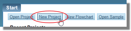
When you are creating a source code project you start the New Project Wizard with the New Project button.
The default options will suffice until the firmware page when we want to select the Create Firmware Project option (not the Create Flowchart Project option). The target family is Arduino and let's choose the controller as the Arduino Yun. The other important options is to make sure that both the Create Quick Start Files and the Create Peripherals options are selected.
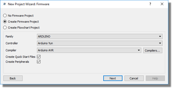
The Create Peripherals checkbox is vital here as it will allow you to choose from all of the prepared shields and breakout boards and will initialize all of the Labcenter peripheral drivers that work with them. If this box is unchecked you will not easily be able to use IoTBuilder in your design.
Default settings for the rest of the New Project Wizard are then fine.
Once complete, you will end up with a source code project in VSM Studio which includes a sizeable amount of pre-generated code. Those who work with MFC or similar will find this familiar but the key thing is not to disturb, change or move the generated code. This is used by the Labcenter drivers and will update as you add peripherals so needs to be managed by the Proteus software. You should ignore this section of code and write your code inside the setup() and loop() routines as normal.
On the schematic you will find a pre-placed Arduino Yun.
Design Phase
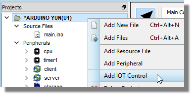
The design of the front panel is identical to that described in the Visual Designer tutorials. You add IoT Controls via the right click context menu on the project tree.
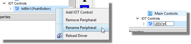
It's always a good idea to immediately rename the button (right click on in in Project tree -> rename command) to something that better reflects it's purpose
You double click on the front panel to open the panel editor and then you drag and drop to place.

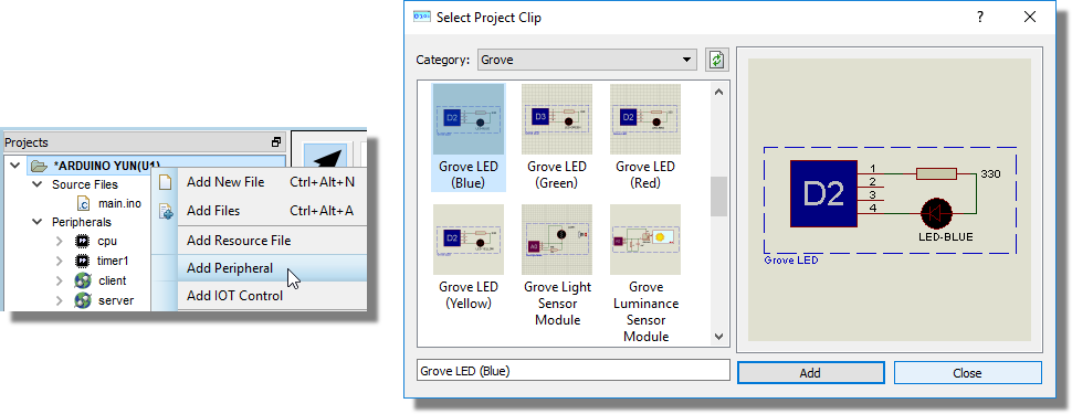
You can also add hardware to your schematic directly from the Add Peripheral dialogue - again on the right click context menu.
Now in the firmware to respond to the button press we need an event handler. Set the button Mode properties in the Main Control to be 'Toggle'. Now, double click on the Main.ino file and set the mouse caret in an empty space (after the void user_loop function) and then drag and drop from the IoT button control onto the source code window. You should get a skeleton control event function into which we can add our button processing code.

Do not change the names of functions or you will break the program. The exception is when you rename the control or peripheral after placing functions on the source window. In this case you'll need to rename the objects and handler prefixes manually or drag and drop them back out again.
What we want to do is toggle the LED based on the state of the button. From the LED peripheral drag and drop the set routine but this time hold the CTRL button down before you drag. Move the mouse inside the button control event routine and then let go to insert at the current mouse position.
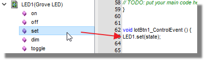
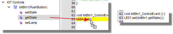
Having dropped the set routine we need to add the boolean parameter depending on whether we are turning the LED on or off. The simplest thing to do is to insert the getState() method of the button which returns the bool that we want - again you can do this by deleting the word 'state' from inside the brackets and then drag and drop the getState() method from the IoT Button control in the project tree.
Having not already set the autoLamp() method on the button itself, we can do this in the code. Drag the setLamp() method below the above code and then again insert the getState() method on to the brackets and set as follows:
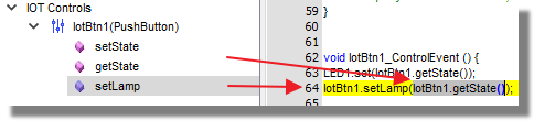
This enables the lamp light to do the same as the LED indicating to the user whether the led is on or off.
That's pretty much it. There are other things we could add but basically this will toggle the grove LED on the Arduino Yun as you press the button on your controller (e.g. mobile phone). We strongly recommend you review the tutorials as the simulation, debug and deployment phases are all near identical to those for a flowchart program.
Summary:
- Don't change or move the generated code at the top of the file.
- If you drag and drop normally the code snippet will insert wherever the mouse caret is at in the file.
- If you hold the CTRL button down while dragging then the mouse caret will move with the drag and the code snippet will be inserted at the caret position when you release the mouse.