Length Tuning Configuration
Overview
Length tuning, or length matching, is often used with higher speed or longer distance signal runs on the PCB to improve signal timing or signal integrity. The basic idea is that the shorter trace follows a detour or meander in order to lengthen it to match the length of the longer trace. This dialogue enables various configurations of serpentine pattern which will then be used when you length match traces on the board.
This is the first tab of the Length Matching dialogue, reached from the Technology menu with the Configure Length Matching command. The other two tabs cover the differential pair cases: Differential Pair Length Matching and Differential Pair Phase Matching.
To length match traces, hold the CTRL button down, make successive left clicks on the traces you want to match and then use the right click context menu to invoke the length match command.
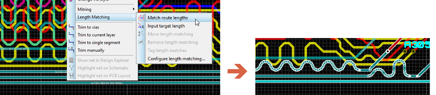
Two routes on a board length matched with serpentine sections
Serpentine Size
These options allow you to specify a minimum, maximum and preferred height for the serpentine tracks, as well as a width between tracks in the serpentine.
Internally, the tuning algorithm will first attempt to route with the preferred height unless an obstruction forces a lesser height. In this case, the height may vary between the preferred height and the minimum height to navigate the obstacle.
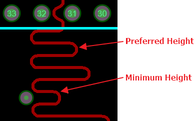
A serpentine dropping from the preferred height to the minimum height to clear an obstacle
If the length match fails because routing with the preferred height is not sufficient then a secondary pass will be made to grow the preferred height towards the maximum height. Be aware that the larger the maximum height, the greater the chance of a long parallel run.
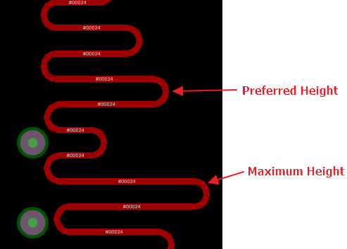
A serpentine grown from the preferred height towards the maximum height
Note that specifying uniform height in this dialogue will impact on these settings, because a variation for obstacle avoidance will not be permitted.
The width is the distance between two sections of the serpentine track in a single switchback. This can also be thought of as the horizontal distance between peak and trough in the direction of travel of the trace.
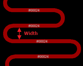
The serpentine width measured between two sections of a single switchback
This value needs to be set quite carefully; if the outbound and returning traces pass too close to each other, crosstalk coupling between the two traces may distort the output.
Units
Every size field on this tab has its own units combo box beside it, offering four choices:
- track width, a multiple of the width of the track being tuned.
- mm, an absolute value in millimetres.
- thou, an absolute value in thousandths of an inch.
- track sep., a multiple of the clearance the design rules require between this track and its neighbours.
If possible, you should try to set serpentine sizes relative to track width. Not only is this consistent with a lot of signal integrity guidance, but it will allow you to set up a single configuration for multiple different tuning operations where the tracks have different widths. The track sep. setting is the equivalent choice when what matters is keeping clear of the neighbouring copper rather than the width of the track itself.
See Also:
External Website: A Summary of Serpentine Routing & Signal Integrity
Cap Style
The cap style defines the topology of the end caps on the serpentine route. Three styles are offered:
- Curved, a rounded cap.
- Mitred, a chamfered cap.
- Squared, a sharp cornered cap.
Curved and mitred caps are both very common. The squared cap is not widely seen as it can cause signal reflections; it is included partly for completeness and also to allow the designer the full range of options.
Matching Tolerance
The matching tolerance is the amount by which a serpentine route is allowed to deviate from the target route it is being length matched against. It has its own units combo offering % target, mm and thou.
If there is a lot of net tuning to be done and it is possible to do so, we recommend specifying this as a percentage of the target length so that the same configuration will hold for all of the tuning operations. If absolute maximum tolerances are needed then you will have to enter the dialogue multiple times as nets are tuned across the board.
When a successful length match is made, you will find the delta between the traces displayed on the status bar.

The status bar reporting the length delta after a successful match
The length matched in Proteus is from centre pad to centre pad. It is not the etched copper length from pad edge to pad edge. Almost all of the time this will either cancel out, where the pad shapes are similar on both sides, or be insignificant. We have chosen this metric because the centre of the pad is the earliest available point at which to start length matching: the route and distance of the signal from the connection point on the PCB to the physical component is unknown.
Uniform Height
There are three options for controlling the shape of the serpentine route along the track: Off, Centred and On.
The default is Off, which corresponds to an irregular serpentine which may be higher in some places than others and may be offset from the centre in some places as well. This option provides the greatest flexibility and therefore the greatest chance of success. It can also help minimise coupling between traces as there may be no defined pattern.
Switching Uniform Height On will clamp the serpentine into a single height, the preferred height, across its entirety. The complete serpentine is allowed to be offset from the centre of the track but is not allowed to vary, as this would involve one section with a different height.
You will need a much higher tolerance to achieve completion if you restrict the length matching to uniform height, as only a complete serpentine will be allowed.
Switching to Centred will force the serpentine to a single size, the preferred height, centred on the original track line. This is the most predictable of the options, but the least flexible and therefore the least likely to succeed if obstacles are encountered.
Minimum and maximum height are ignored and disabled with a uniform height setting. The uniform height will be the preferred height.
Restrictions on height and offsetting will severely limit the ability of the length matching algorithm to successfully complete. As you can see from the pictures above, any obstacle will result in failure because the serpentine is not allowed to change shape to work around it.
See Also: