Displayed Layers
Overview
This dialogue form allows you to choose the layers that are displayed and provides a live update on screen of the currently selected layer set.
It also allows you to set up and save different layout views and assign them to keyboard shortcuts. This in turn makes it easy to switch between, for example, a top view of the board, a bottom view of the board and a full board view.
A layout view is simply a saved set of colours and visibility settings corresponding to the selection of the options on this dialogue form. Three views are supplied as standard: BLACK_PAPER for normal screen work on a dark background, WHITE_PAPER for a light background, and MONOCHROME for printing. For the majority of users these will suffice without modification, although you may well want to create your own to suit your working preferences.
The dialogue is reached from the View menu with the Edit Layer Colours/Visibility command (CTRL+L), and it is the first tab of the Colours and Display Settings dialogue. The second tab, Thru-View Settings, carries the graphics mode and the layer opacity settings.
Options
Layout View Colour Sets
Layout views allow you to configure various different layer visibility options into named groups, including paper colours and solder resist/paste mask visibility. You should then assign a layout view to a keyboard shortcut for easy access. Typical examples might be:
- ALL : All of the layers turned on.
- TOP: Top copper, top silk, top resist, top paste, ratsnest, board edge.
- BOT: Bottom copper, Bottom silk, Bottom resist, Bottom paste, ratsnest, board edge.
- INNERX: selection of inner layers in use with the current project.
- TOPASSEMBLY: Top Assembly layer, Edge Layer and Draw Component Assembly Checkbox. Maybe a mech layer if additional info is there.
The controls in this group are:
- Layout Views, the combo box that selects the view you are looking at and editing.
- Keyboard Shortcut, a number from 0 to 9 that recalls this view directly from the keyboard.
- New, which creates a further view and prompts you for a name.
- Rename, which renames the selected view.
- Delete, which removes the selected view.
- Reset, which restores the selected view to its supplied colours and visibility settings.
Rename and Delete are greyed out for the three supplied views, which is why BLACK_PAPER, WHITE_PAPER and MONOCHROME cannot be removed. You can still change their colours, and Reset will put them back as they were.
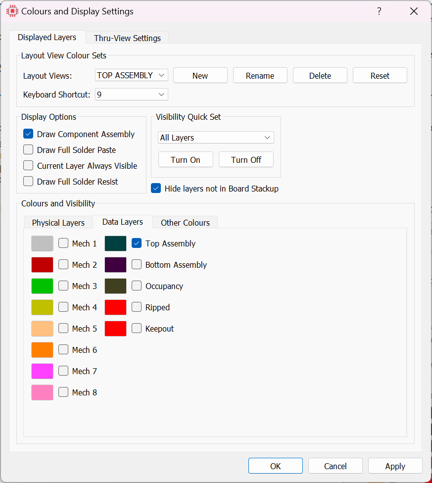
Displayed Layers set up for Top Assembly view. Note the keyboard shortcut, which makes toggling between a full board view and an assembly plot a single keystroke.
You can set layers from all three of the layer group tabs when creating a layout view, then use the Apply button to commit. For example, in the Top Assembly view above the top assembly data layer is selected and so is the board edge on the physical layers tab.
See Also:
Display Options
- Draw Component Assembly, when enabled, the automatic component assembly plot information will be drawn as will any manual component assembly information stored in a package. This is useful mainly in an assembly plot view, or where silkscreen idents are suppressed. Component assembly graphics are not selectable or movable directly; you must select and move the component.
- Draw Full Solder Resist, when enabled, a full solder resist including pad expansions is displayed on screen. You can adjust the brightness of this layer with the Solder Resist Layers opacity slider on the Thru-View Settings tab if you are working in hardware accelerated mode.
- Draw Full Solder Paste, when enabled, a full paste mask including pad coverage is displayed on screen. You can adjust the brightness of this layer with the Solder Paste Layers opacity slider on the Thru-View Settings tab if you are working in hardware accelerated mode.
- Current Layer Always Visible, a checkbox designed to prevent unintended arrival on an invisible layer during route placement. For example, you start routing with TOP_VIEW on top copper and then via down to bottom copper, which is invisible in the TOP_VIEW layout view. With this checkbox enabled bottom copper would turn on when it became the current layer.
- Hide layers not in Board Stackup, a checkbox that removes copper layers not in the current board stackup, simplifying the physical layers tab of the dialogue form.
Visibility Quick Set
This group provides quick set and clear options for all of the layer checkboxes, or for a subset of them. Choose the scope from the combo box, then use Turn On or Turn Off.
Colours and Visibility
Each layer has a checkbox and a colour selector. When the checkbox is ticked the layer will be visible on the layout. There are three tabs: Physical Layers corresponding to the actual board, Data Layers providing additional information, and Other Colours for miscellaneous items.
The colour of any given layer can be changed by clicking on its colour selector and adjusting as required. Some care is required if the paper colour is being changed, to ensure that a sensible result is achieved where colours overlap, for example traces on different layers. As a general rule of thumb, if you choose a light paper colour as in the WHITE_PAPER view then choose secondary colours for the specific layers, whereas with a dark paper colour as in the BLACK_PAPER view you should choose primary or strong colours for the layers.
The Other Colours tab also carries two visibility checkboxes rather than layers: Ratsnest, which shows or hides the ratsnest connections, and Force Vectors, which shows or hides the force vectors used during placement.
Remember that the colour changes, and the layer selections, are part of the currently specified layout view. If you are only working with one layout view then it does not matter, but otherwise make sure that you are adjusting the view you mean to. The layout view combo box is at the top of the dialogue.
See Also: