PERFORMING A DXF IMPORT
Generating the DXF File
The DXF file to be imported should be generated by the mechanical CAD application you use. Consult the documentation or on-line help associated with the CAD application to determine how best to do this.
As far our import converter is concerned, the only requirements are that:
- The file exported by the application be in plain ASCII and not in the alternative binary (DXB) format.
- DXF release R14 or later is preferred. Earlier releases may not carry the drawing units, in which case you must set the scaling manually.
Convert to Copper
The Convert to Copper option allows you to bring in graphic lines that will be translated into traces in the Proteus layout. You can also bring in a filled object which will be translated into a power plane object if this option is selected. This provides a really useful method to import antenna designs and other similar route topologies.
You cannot bring in nested polygons with convert to copper selected. This is because the closed path detection pass, which is what would resolve the nesting, is not applied when the import is converting to copper, so the Detect Closed Paths option and its tolerance have no effect in this mode.
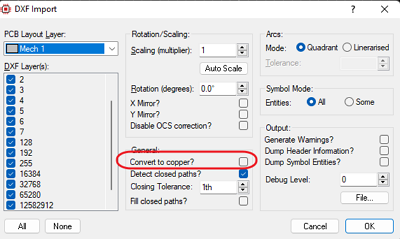
Convert to Copper attempts to make traces or zones from imported graphics objects.
To import as copper:
- Select a copper layer as the target import layer
- Remove any un-necessary layers in the DXF. The simpler the imported data the more likely it is that we can convert.
- Select the Convert to Copper checkbox on the dialogue form and proceed with the import.
- Assign a net to the imported objects. For zones you simply edit them and assign to net. For traces you should place a pad/via on the end and then route to them from an object on the net.
Importing onto Solder Resist (soldermask) Layers
First, note that you can automatically expose power planes in their entirety via a checkbox on the Edit Power Plane dialogue form. This is both dynamic (updates as power plane flood changes) and precise and is therefore a much better solution when you want to expose the entire plane.
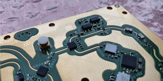
Exposing resist plane to ensure good contact with custom Aluminium case with cavity for RF isolation purposes.
However, it may be necessary to import a complex shape onto the resist layer to form a solder mask opening. You can do this with DXF import, although nested polygons are not selected.
To import as a resist opening:
- Select the appropriate resist layer as the target import layer.
- Remove any un-necessary layers in the DXF. The simpler the imported data the more likely it is that we can convert.
- Make sure Detect Closed Paths is ticked and tick Fill Closed Paths as well. Only filled shapes constitute keepouts on the resist layer.
- Import as normal. You may need to change the closing tolerance should your DXF paths not be fully closed.
Layer Assignments
Having generated the DXF file you must now decide where its contents are to land. Each import targets a single layout layer, which you choose from the PCB Layout Layer combo at the top of the DXF Import dialogue form. The DXF Layer(s) list beside it shows every named layer found in the DXF file, and everything you tick there is combined onto that one layout layer.
If the drawing carries data for several different layout layers, for example a board outline that belongs on Board Edge and a cut-out detail that belongs on a mechanical layer, run the import once per destination layer and tick only the DXF layers that belong there each time. Layer selection is the one decision worth making before you start, since it is far easier to import twice than to move the imported graphics afterwards.
The individual fields are documented in the Import DXF dialogue form topic.
Basic Conversions
To perform a DXF file conversion you need to load the converter with the name of the DXF file to be converted. This process is implicit with Proteus in that immediately on selecting the Import DXF tool you will be asked to open the appropriate DXF file. A successful loading of the file will result in the appearance of the DXF Import dialogue form.
The one option on that form which changes the geometry you end up with, rather than merely what is imported, is the Arcs setting. Its Mode radio buttons offer:
- Quadrant, which splits an arc into quadrant arcs and reproduces it as a true curve. This is the default and is normally what you want.
- Linearised, which approximates the arc with a series of straight line segments. The Tolerance field beside it sets the accuracy of that approximation, and is enabled only when Linearised is selected. A lower tolerance produces a closer fit and more segments.
Choose Linearised only where the receiving process needs straight segments, since it produces a heavier drawing and loses the true arc.
All of the remaining fields on the dialogue form are documented in the Import DXF dialogue form topic.
Conversion Errors
With regard to DXF file parsing errors, the converter has been written to be as fault-tolerant as is consistent with reading a DXF file. Parsing errors are only generated when:
- The DXF file doesn't contain an ENTITIES section. A DXF file without entities is deemed 'empty', which makes conversion impossible.
- The DXF file contains a section (e.g. HEADER, ENTITIES) or a primitive (e.g. LINE, CIRCLE, etc.) that doesn't contain a single record. All sections should at least contain an end-of-section record and all primitives should contain at least one record. This implies the DXF file is corrupted.
- The end of a BLOCK entity in a non-BLOCKS section or the end of the BLOCKS section before the end of a BLOCK entity. This implies the DXF file is corrupted.
- The failure to extract (parse) data of a type consistent with the group record code. For example a record with a group code of 10 implies an integer value and a record with a group code of 41 implies a floating point value. An error is generated if (regardless of formatting) a value cannot be parsed.
Whenever an error occurs the converter reports the error in the form:
ERROR (000413): Entity Group Expected - EOF found?
and the conversion is aborted.
For file parsing errors, the number of the last line read from the DXF file is shown in brackets after the ERROR keyword (note that the converter reads whole groups of two lines from the DXF file at a time, so any error may be on the line indicated or on the preceding line). For non-parsing errors, the line number is displayed as dashes.
Conversion Warnings
Apart from errors (described above) all other reports of unusual or possibly erroneous conversion behaviour are treated as warnings. Warnings are not fatal (they do not stop the operation and completion of the converter) but are useful if the resulting region file is not what was expected. In order to be complete, the converter issues warnings whenever it encounters a situation that may or may not lead to unusual region files and this includes any record it reads and discards as being either of unknown purpose or unconvertible. Warnings are only generated if requested (through the Generate Warnings checkbox on the dialogue form).
Warnings are displayed in a similar format to errors (described above) except that the DXF file line number line and message text is preceded by the word WARNING. Generated warnings are available for viewing in two log files, which are written to different places. DXFCVT.LOG holds the conversion log and is written to the current working directory. DXFINFO.LOG holds the results of the initial parse that reads the layer names and units, and is written alongside the design file. Because that parse runs first, DXFINFO.LOG is generated even if the import is abandoned before the dialogue form appears.
See Also: