CO-ORDINATE SYSTEMS
Overview
The fundamental unit of linear measurement in Proteus is 10nm (ten nanometres). Given 32 bit representation of the co-ordinates this allows a board size up to +/- 10m (ten metres) with some headroom for calculations. The 10nm unit divides exactly into both 1um (micron) and 0.1 thou (one ten thousandth of an inch) giving exact representations of both imperial and metric dimensions to these resolutions.
Rotational angles are stored to 0.1degree.
The co-ordinate display can be switched to reading metric units by invoking the Metric command or via the keyboard shortcut (by default this is the M key). Restoring imperial mode is achieved by invoking the Metric command again.
The display can also be switched between cartesian and polar co-ordinates with the Toggle Polar Co-ordinates command on the View menu (default key Z). In polar mode the co-ordinate readout gives a radius and an angle measured from the current origin rather than an X and a Y, which is convenient when laying out pads or mounting holes on a circle. Several tools follow the display: Move To accepts a radius and angle in polar mode, and Measure Mode reports radial and circumferential components in place of horizontal and vertical.
You can set up default units for a template via the Set Grid Snaps command on the Technology Menu. When you instantiate a project from a template these settings are then applied. Note that this affects only the units which are set when you open the project (the start up units).
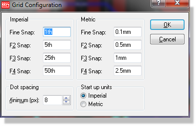
Setting the snap grids and the default start up units
Dimension Entry Fields
A number of the dialogue forms contain fields that deal with dimensions such as pad style sizes, track widths, design rule clearances and so forth. All these fields are handled in such a way that both metric and imperial units can be used at will. The operation of these fields is in accordance with the following rules:
- Values are displayed in units chosen by a heuristic algorithm which detects whether a dimension is a whole number of imperial or metric units. Thus 25.4mm (however originally entered) will always display as 1in, when the field first appears.
- Displayed values always carry a unit. If you delete the existing value, the original displayed unit will be used.
- If you prefer, you can enter a new value with an explicit unit. Valid units are:
Units Description th
Thou (10e-3 inch) mil
Thou (10e-3 inch), an alternative spelling of th in
inch ft
foot (12 inches) yd
yard (36 inches) nm
nanometre (10e-9 metre) um
micron (10e-6 metre) mm
millimetre (10e-3 metre) cm
centimetre (10e-2 metre) m
metre - Two shorthand suffixes are also accepted: ' for feet and " for inches.
- Whatever units are chosen, values must be less than +/- 10m, and are held at a resolution of 10nm.
Output Origin
For CADCAM output in particular, but also when working on a board which has to fit into a pre-designed mechanical casing, it is useful to be able to define a reference point on the board which relates to the mechanical design's co-ordinate system. The output origin defines this point within the layout editor, and is drawn in blue on the Editing Window as a target symbol.
- You can re-position the output origin using the Set Output Origin command on the Output menu.
- The output origin does not affect the co-ordinates used in Region files.
False Origin
Although the Toggle False Origin command appears on the View menu, it should only be used via its keyboard short cut (default key is O). Its function is to zero the co-ordinate display at the current mouse position, a feature that is most useful when laying out a complex pattern of pads given a set of dimensions on a drawing of the component.
When a false origin is set, the co-ordinate display changes colour from green to magenta as a reminder.
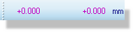
False Origin set to 'ON'
Cancelling a false origin is done by invoking the Toggle False Origin command a second time.
Grid Display
The Editing Window includes a grid display by default. This can be toggled between ‘off’, ‘dot display’ and ‘line display’ via the ‘G’ button on your keyboard. The spacing of the dots normally equals the current snap setting (see below), but if you are zoomed out a good way, it will be multiplied by a factor of 2,4,8 etc. The threshold at which this occurs can be adjusted on the Set Grid Snaps command on the Technology menu.
The grid dots on the Overview Window are 0.5in apart.
Snapping Grids
Although the motion of the mouse arrow itself is smooth, you will see that the co-ordinates normally jump in fixed multiples of, for example, 50 thou. The size of these multiples is set by the Snap commands and the purpose of this is to facilitate the placement of objects on a fixed grid.
Under normal circumstances, boards tend to be routed on a 50 or 25 thou grid.
Three snap grids for each of imperial and metric modes are available at any one time, though you can redefine their values using the Set Grid Snaps command on the Technology menu. The current snap options are selectable from the View menu or by using shortcut keys (the preconfigured keys for the snap commands are CTRL+F1 & F2-F4).
The snapping points are computed starting from the current origin as set by the Toggle False Origin command. This provides the means to measure out pad placement for a new component, since you can set the origin at the first pin, set one of the snap values to the pin spacing, and then advance the cursor along the pad positions using the cursor keys.
Real Time Snap
As well as snapping to the grid dots, the layout will also snap the cursor to pads and/or tracks which lie off the currently selected snap grid. This process takes place in real time - as the pointer is moved - hence the name Real Time Snap.
The rules for what is snapped to are as follows:
- Pads are always snapped to. Only pads whose layer range overlaps the current layer range are scanned.
- Tracks are snapped to when the either the Trace icon or Via icon is selected. Only tracks on the current layer are scanned.
- Ratsnest lines are snapped to when the Ratsnest icon is selected.
- The range within which the pointer will 'see' an object is either half the current snap spacing or, if grid snap is disabled, the actual bounds of the object concerned.
RTS is extremely useful when routing between components whose pins are on different grids, since it alleviates the need to constantly switch between routing grids. In this context, the Trace Angle Lock feature is also very important.