DIFFERENTIAL PAIR ROUTING EXAMPLES
Example: Routing a Differential Pair on a Single Layer
This is the simplest of all cases and perhaps also the least likely to happen in practise.
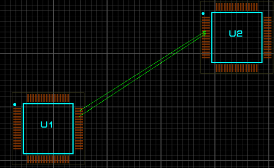
Both components are on the same layer and the diff pair tracks are also on that layer (i.e. no vias)
Setup
The setup and configuration are standard and as described in the topic linked below.
Routing
Always try hard to rotate (or re-map) such that diff pair ratsnest lines are not crossed. Crossed ratsnest lines will make for very awkward entry at the receiver.
We start by selecting diff pair routing mode and then click on one of the target pins of the source / driver device. Direction is important for phase matching so you want to route from source to receiver. At this stage Proteus will automatically route an exit from both source pins and we can continue routing both tracks as though we were routing a single fat track. We move the mouse to a destination pin and left click to finish routing. Again, Proteus will automatically route from both tracks to the terminating pins and complete the route. Finally, when the route is complete phase matching on the tracks is performed to equalise their lengths.
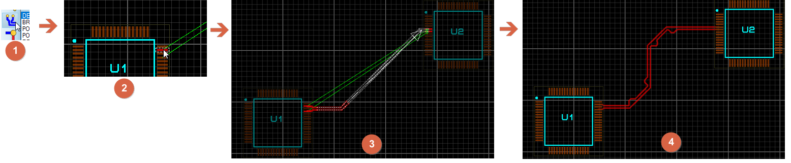
Routing a pair on a single layer, from the source pins through to the phase matched result.
Example: Routing a Differential Pair with Vias
This is a far more common situation where you either want or need to route the differential pair on a different layer than the source/receiver pins. In our test jig below we are working with a BGA and will need to escape onto an inner layer for diff pair routing.
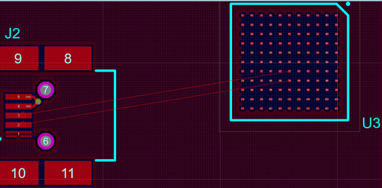
Manual fanout is required here, and keeping the two escapes symmetrical matters for a pair.
Setup
Follow the standard setup and configuration as described in the topic linked below.
Routing
The first routing task is the fanout from the source pins and the destination pins. We do this manually, using normal routing mode. Fanning out a differential pair by hand is worth the effort because the two escapes need to mirror each other: matching via positions and pad entries keep the pair in phase before the coupled run even starts.
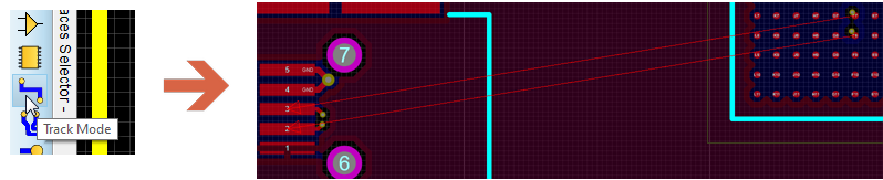
Manual fanout in normal routing mode to set up the routing layer for the diff pair.
Note that when we pick up the route in diff pair mode it will automatically find the pairing distance so we don't need to be absolutely precise with the fanout.
Next, switch to differential pair routing mode and click on one of the vias routed from the source pins (direction of routing matters for phase matching). Route towards the receiver pins (hold CTRL down for curved routing). Either press ENTER to auto-complete or route all the way and left click on one of the vias connected to the receiver.

Routing in differential pair mode, with ENTER to auto-complete and CTRL for curved corners.
A couple of notes about routing if you need to change direction:
- An 'S' configuration will to some extent naturally bring things back into phase as you are cornering in a different direction the second time from the first.
- Leave a straight segment between curved corners if you can. Phase matching serpentine segments can only occur on straight segments.
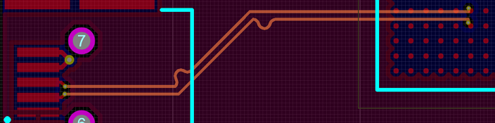
Where Phase Matching is required it will be applied automatically on the next straight segment after a corner.
When you complete the route the phase matching will take place automatically and the lengths of the two tracks will be equalised after each corner and, depending on your fanout, possibly at each end of the route.
Remember that phase matching depends on direction so you may need High Speed Design > Reverse route direction on the track context menu if you have routed receiver to source.
See Also:
Example: Routing a Differential Pair with Branched Passives
This case is much the same as the previous one except for the routing topology. Here we tap off the diff pair routes to a passive device (or devices) rather than insert one in the middle of the diff pair.
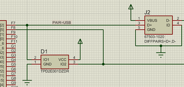
The passive is tapped off the pair rather than inserted into it.
Setup
Follow the standard setup and configuration steps. While we've wired on the ESD device it doesn't split the diff pair so we only need one pair and no extra configuration is required.
See Also:
Routing
Follow the basic routing procedures documented in the previous samples to first fanout from the source / receiver pins in normal routing mode and then route them together in diff pair routing mode. After the diff pair is routed position the passive device and connect it using standard routing mode.
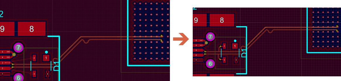
Route the diff pair and then place and wire any passive branches.
Important Note:
Nothing in this process monitors the stub lengths from the passive device(s) or what their effect might be on the differential signal. The only action taken by Proteus with respect to these branches is to ignore their lengths for the purposes of the differential pair report and the pre-production check testing. Branched passives create stubs off one or both lines; you should still keep stubs as short as practical or place components inline to avoid degrading the pair.
Example: Manual Differential Pair Routing
It is always possible to route the differential pair manually and then engage the phase matching from the context menu. This means that if the diff pair routing algorithm can't cope with your board topology you can still complete the pair.
Setup
Follow the standard setup procedures
See Also:
In particular, the design rules are critical here because you will be routing the two tracks separately.
Routing
Route the first track in normal tracking mode and then route the second track, hugging it to the first one.
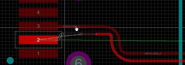
Route the second track manually hugging the mouse to the first one.
Once complete, right click on one of the tracks and select High Speed Design > Phase-match diff. pair from the resulting context menu.
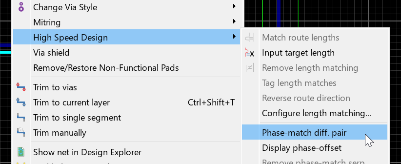
Phase match manually after you have completed both routes.
Please let us know if you have to revert to manual routing of diff pairs. If you are able to send us use cases where the assisted mode fails ([email protected]) that would be a great help to us in improving the differential pairs routing algorithm.
Remember that phase matching depends on direction so you may have to use High Speed Design > Reverse route direction first. You want to phase match from source to receiver. The differential pairs report will show you the routing direction that Proteus has for the tracks.
Example: Length Matching Differential Pairs
You can use the length matching technology in Proteus to match a differential either to another differential pair or to a target length.
The first step is to configure the shape and style of the serpentine segments. You can do this from the differential pair tab of the length matching dialogue form.
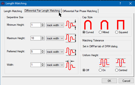
Length Matching Configuration
You'll find detailed context sensitive help on each field via the question mark at the top right of the dialogue form.
Once we've set the topology for the length match segments we need to set up the tolerance. Since this is normally specific to the protocol you are working with it is set in the design rule manager and associated with a net class.
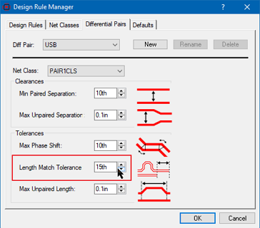
Length Match Tolerance.
Now that the setup is complete we can do the actual length matching. To match to a specific distance right click on one track in the differential pair and select High Speed Design > Input target length.
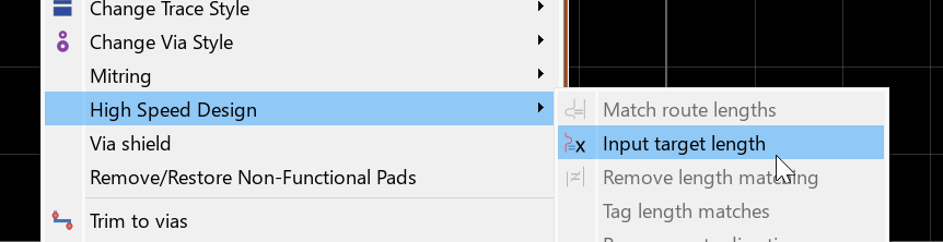
Set the target length for the differential pair.
Alternatively, to match against another differential select one track on the diff pair and then hold the CTRL button down and select one track on the other differential pair. When you have a track selected on each diff pair right click on either one of the tracks and select High Speed Design > Match route lengths from the context menu.
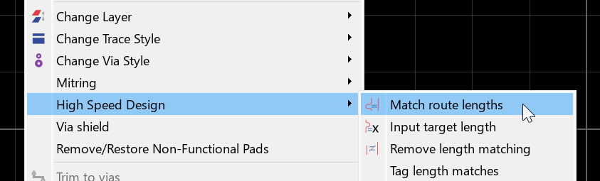
Matching the length of two diff pairs to each other.
Phase Matching vs Length Matching
- Phase matching (or skew correction) is the correction of the lengths in a differential pair against each other. Almost always this happens after a corner where the outside track becomes longer than the inside track as the routes traverse the corner.
- Length matching (or tuning) is controlling the distance of both routes in the differential pair. Serpentine segments are added to both routes in sync in order to lengthen the differential pair to either a target distance or to another differential pair.
There is an interaction between length matching and phase matching that can occasionally cause problems. Since length matching adds serpentine segments it adds corners which causes the length of tracks in the diff pair to be different and out of phase. Fortunately, anything approaching an 'S' shape will auto-correct as the longer track on the first corner becomes the shorter track on the second corner.
When you length match a diff pair Proteus will first perform the length matching and it will then perform an automatic phase matching. What this means is that if the length matching requires phase matching then the phase matching itself may add slightly to the length. This is where both tolerances and placement become important. The designer needs to be aware of tolerances and may even need to tweak them when length matching to prioritise either phase or length. Placement is also hugely important and can help a lot to reduce phase mismatch during routing.
See Also:
Example: Routing a Diff Pair with Pass-Through Components
A pass-through component is just a passive on the diff pair line where two pins are on the same line and therefore through which the signal will pass. These should be placed and wired on the schematic in the normal way.
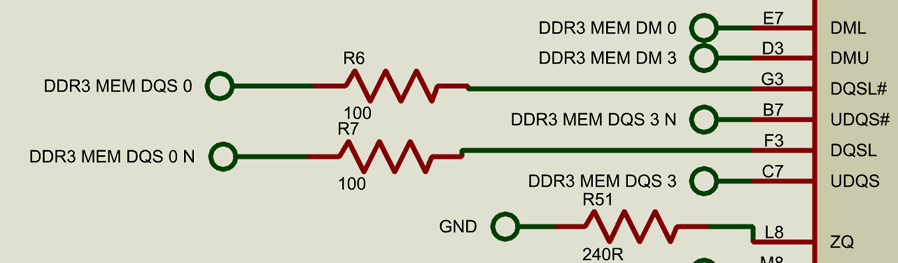
Add the pass through components on the schematic in the normal way.
Then, right click on one of the diff pair lines and select the diff pair configurator from the resulting context menu.
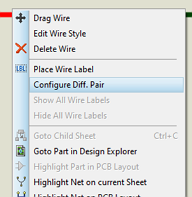
Launch the configurator from the context menu on one of the diff pair wires.
The start and end of the diff pair should be set up in the normal way and then the manage passthrough button can be used to specify which components and pins should be considered as part of the DP.
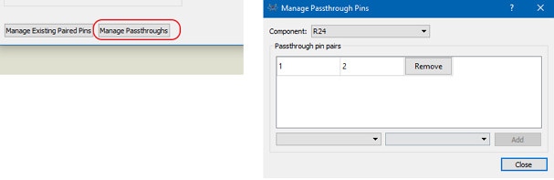
Select and specify Pass through component
Then, on the layout side place the passives in position as you would normally. It may be necessary to fan out from the pads if the routing will take place on a different layer and this should be done manually.
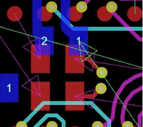
Place the pass through components in position and handle any required fanout vias.
Finally, switch to the diff pair trace mode and selecting the required routing layer, you can complete the tracks as normal.
Length Calculations
When a pass through component is used in a diff pair it affects the length of the pair. Proteus constructs the diff pair length from the following:
1) the etched length of copper on the board (the tracking)
2) the specified internal length of any pins
3) the straight line distance on the PCB between the pads of the pass through component.
Number 2 is specified by adding internal lengths to a component on the PCB whereas both 1 and 3 are calculated automatically by the system.
The differential pairs report will show both the etched and the total length for each routed pair where the total length is the contribution from numbers 2 and 3 above.
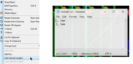
Adding internal lengths to a pass through component.
You can length match differential pairs with pass through components in them in exactly the same way as you would normally.