GERBER VIEWING
Overview
Since board manufacture and design iteration can be both time consuming and expensive, it is useful to be able to view Gerber files to ensure that all is well prior to sending them to the bureau.
To facilitate this, Proteus includes a Gerber View command which will load and display selected files produced by the CADCAM command.
To view Gerber output files
- The Gerber Viewer is part of the application icons. Click on the icon to open the Gerber Viewer in a separate tab.

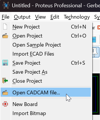
- To open a Gerber fileset, go to the File menu and select Open CADCAM file... and load a <file name>-CADCAM READ-ME.TXT.
- Proteus will then parse the file and display a dialogue form for selecting which layers to view. By default, all available layers are loaded.
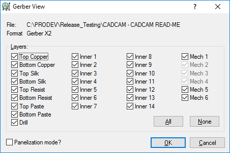
The Gerber Viewer will accept both RS274X Gerber and also Gerber X2 filesets, although it will be of far more use with Gerber X2 as it can correctly identify blind/buried vias.
When you export Top and Bottom Assembly Layers with Gerber X2 they import to the Gerber Viewer as Top Assembly and Bottom Assembly layers under their own names. You can then control their visibility from the View Menu > Layers command.
Editing Gerber Data
Although it is possible to perform editing operations on the Gerber View data, we do not recommend or support this mode of operation, aside from panelisation which is discussed in the next section.
Although integrated with Proteus The Gerber module is not the place to make edits to your layout. If you spot something that needs altering or removing then you should do so inside the layout editor and then regenerate the Gerber/Excellon files.