Creating New Packages
APPENDIX: Creating New Packages
Proteus comes pre-supplied with a large quantity of footprints, and we have seen previously how to select and place these parts on to a layout. However, it may be necessary at times to create your own custom footprints or symbols – also a simple task with Proteus – and this process is detailed below.
While the following topics are a detailed explanation of how to create component parts in Proteus, in practise this should almost never be necessary. In addition to the many installed libraries the universal part importer provides support for almost all third party part vendors (Ultra-Librarian, Samacsys, SnapEDA, etc.). If the part doesn't exist in Proteus itself the next step is to search for and then import it directly from a third party vendor. This is discussed in some detail in the importer help file and shown on our Youtube Channel.
See Also:
Drawing the Footprint
In our example, we will create a SQFP44 footprint with 0.8mm pitch and 12mm width. You may also wish to refer to the more advanced video tutorials linked below:
Creating Button Pads / Membrane Touchpads with custom paste and resist.
Creating QFN Parts with Thermal Pads and patterned Paste Mask
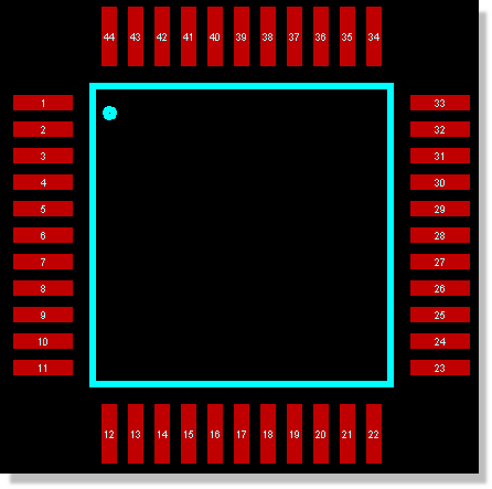
Finished SQFP44
Start by selecting rectangular SMT mode. We want a pad 0.5mm by 1.8mm that should already exist as M0.5x1.8.
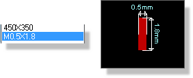
The Pad used in the M0.5x1.8
If the pad style does not exist you can easily create it as discussed earlier in the tutorial (Click on the ‘C’ button above the Object Selector).
Make sure that the Layer Selector is on Top Copper and place one of the pads in the usual way. Right click to cancel placement immediately after placing a single pad and then left click on the pad to highlight it. With the pad highlighted, go to the Edit Menu and select the replicate command. Alternatively you can right click on the pad and select replicate from the resulting context menu.
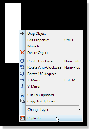
Right click and select the replicate command
The replicate command will action on tagged objects so you should ensure that you have only the placed pad highlighted before invoking this command.
There are 11 pads on each side of the footprint so we need to replicate 10 times with an X-Step of 0.8mm as per the following screenshot.
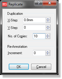
Replicate Dialogue
Note that you need to include the units of either millimetres (mm) or Thou (th) when entering values in to the X/Y-step fields.
This will give us a single row of pads of the correct pitch (zoom in, change the snap settings and measure if you would like to confirm). The next step is to duplicate this row of pads to form the bottom of the footprint.
Start by right dragging a tagbox around the entire row of pads and then go to the Edit menu and select replicate. This time we want only one copy, 12mm down (or up) from the current row. Use negative co-ordinates if you want the duplicated row beneath the current one or positive co-ordinates if you want it above.
We now need to repeat the process with the other two rows. Drag a tagbox around a full row, right click inside the tagbox and select Block Copy from the resulting context menu.
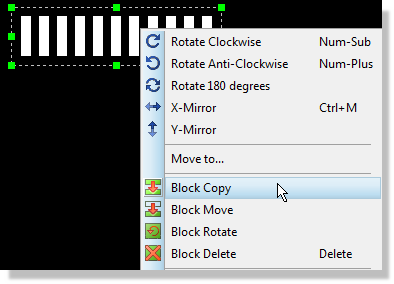
Block copy will copy everything inside the tag box
Move the mouse and drag the copy to a free area, left clicking to place and then right clicking to exit copy mode. Now, drag a tagbox around the row, right click and select the Block Rotate option, specifying a 90 degree rotation to align the pads correctly.
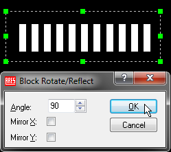
Block rotation of 90 degrees
In order to position this row of pads correctly it’s best to first set place a marker on the location we want to move the row of pads to. For this footprint the centre of the top pad on the left hand side is 2mm below and 2mm to the left of the centre of the left hand most pad on the top row. This gives us enough information to accurately position the row.
Select marker mode in preparation and then move the mouse over the left hand most pad on the top row until it is encircled. You’ll want to be on a fairly precise snap setting for this (e.g. 0.5mm or F2 shortcut key).
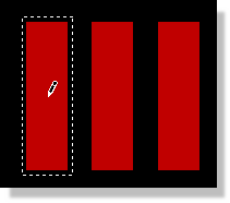
Make sure the pad is encircled
If you find your snap settings in thou you need to switch to Metric mode, either by hitting the ‘M’ key on the keyboard or via the Metric option on the View Menu.
Now, hit the ‘O’ key on the keyboard to set a false origin at this location and then invoke the Goto-XY command from the View Menu.
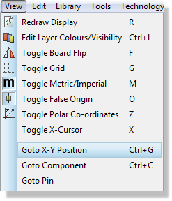
Type in –2mm in both the X and the Y co-ordinate fields (i.e. down and left) and make sure that the offset is relative to the current origin. Select OK and click the mouse twice to place the marker at this location.
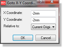
OK will take the mouse to the specified location
The marker we have placed will serve for now as the location we want to centre the top most pad of our third row. Simply draw a tagbox around the row, left depress the mouse inside the selection box and drag into position. You will almost certainly need to use the zoom commands (F6,F7 or the middle mouse wheel) and possibly also adjust the snap setting (CTRL+F1) to get accurate positioning.
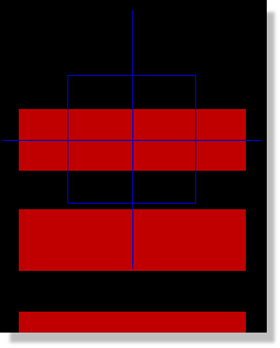
Moving the centre of a pad on to the marker
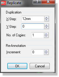
Having placed the row of pads right click on the marker and delete it – we’ll come back to marker placement later on. The final stage of pad placement is to replicate the newly placed row of pads onto the right hand side. As before, draw a selection box around the row of pads and use the replicate command with an X offset of 12mm to duplicate the row.
Adding the silkscreen graphics is now straightforward. Select the 2D Graphics Line icon, make sure the Layer Selector is on top silk and place four lines along the inside edges of the pads to form a box. You’ll find this much easier to do if you change the snap settings upwards (e.g. F2).
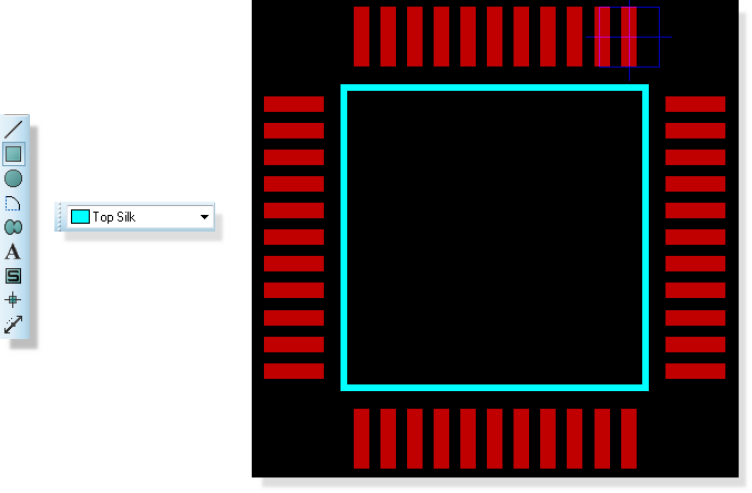
Placing the Top Silk area
The next job we have is to number the pads. Start by invoking the Auto Name Generator from the Tools Menu. We don’t need to enter anything in the string field here; simply leave the defaults and click on the pads consecutively to number them, Number 1 is the top pad on the left hand row.
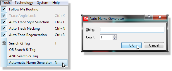
Auto Name Generator
Remember to hit the escape key on your keyboard when you have finished numbering pin 44 to exit assignment mode.
It’s common to place a small dot beside pin one and you can do this via the 2D Graphics circle icon. Make sure that the Layer Selector is on Top Silk and turn the snap setting down to minimum (CTRL+F1) to achieve finer control over the size.
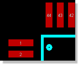
Place a small dot where Pin 1 is
The final step is to specify where we want the origin of the device to be (for placement purposes) and where we want the silkscreen graphics for the package reference to appear. Both of these are done with markers.
Select marker mode and make sure that ORIGIN marker is highlighted in the Object Selector. You’ll recall that we used this as a reference point earlier but it’s real job is to specify the origin of the component for placement and rotation. This is really a decision for the user but typically the origin is either pin 1 or the centre of the component. For simplicity here, we will place the origin on pin 1; left click to begin placement, move the mouse over the centre of pin 1 and left click again to commit the origin marker.
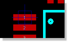
Origin marker placed
Now, change the marker type to be REFERENCE in the Object Selector. The Reference marker dictates where the component reference (e.g. U1, R12, C3) is placed by the software relative to the component. Again, this is very subjective but we’ll set it above and slightly to the left of the part.
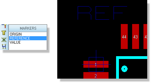
Reference marker placed
Having completed the layout of the footprint, we can now move on to the (far simpler) process of packaging the part into the libraries.
Circular Pad Placement
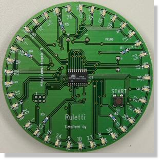
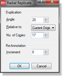
The replicate command is dynamic based on whether you are in cartesian co-ordinates or polar co-ordinates (View Menu Toggle). If you needed to place pads in a circular shape you would:
- Select Polar mode (View Menu).
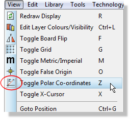
- Place a False Origin ('O' shortcut key).
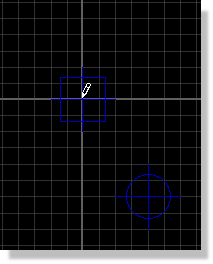
- Orient your first pad and place at radius distance
from (false) origin.
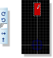
- Right click on the pad, select replicate comm
and and specify angle (e.g. 20) and number (e.g. 17) to complete the
circle.
Packaging the Footprint
Drag a selection box around the entire footprint and then select the Make Package command from the Library Menu.
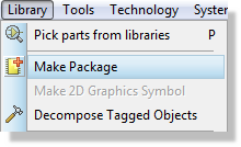
Launch 'Make Package' from the Library menu
The first screen is fairly self-explanatory and similar to that we’ve seen in the schematic application. Note that the package description is searchable when we are browsing for footprints so a little effort to make this as descriptive as possible is worthwhile. You will also want to create the part in the USERPKG library which is the default library supplied for user footprints. For our purposes, we’ll call this package TESTPKG and give it some basic entries.
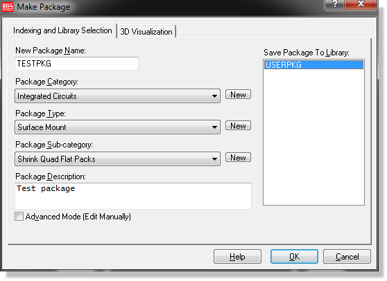
The Make Package dialogue form
You can create your own libraries via the Library Manager – please see the reference manual for details. You should not make your own parts into the other pre-supplied libraries as Labcenter may overwrite these libraries during upgrade installs.
When this is filled out, switch tabs to the 3D Visualisation tab (do not hit the OK button at this stage – we still have some work to do). Essentially what we need to do here is provide as much information as possible in order to get a sensible 3D image of the part which can then be used when we use the 3D Viewer to examine a board. This job is greatly aided by a 3D Preview on the dialogue form that will update live as we adjust parameters. Discussion of parameters and values is beyond the scope of this tutorial and is discussed in some depth in the online reference manual (Help Menu Reference Manual). For our purposes, simply fill out the property fields as shown in the next section.
3D Visualisation
This is where you would either provide a STEP file or use the Labcenter script to provide a geometric model for the part. In either case, you will get a 3D representation of the part in the 3D Viewer and can then export to Solidworks or other MCAD toolchains for case and mounting design.
If you are providing a STEP file you must:
1) Download the STEP file from the internet and place in the MCAD directory of your Proteus installation.
2) Import via this dialogue.
3) Rotate and offset such that the part is aligned correctly on the 2D courtyard. Note that you can zoom in and out on the preview with the middle mouse wheel (or buttons) and the flip command will mirror the board at its current position.
Fortunately, this job is greatly aided by the number of STEP files available on the internet (e.g. www.3dcontentcentral.com) and a 3D preview on the dialogue form to help with alignment.
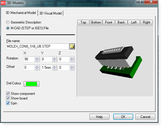
Setting the 3D parameters
Discussion of geometric model parameters, values and importing models is beyond the scope of this tutorial and is discussed in some depth in the online reference manual (Help Menu – Reference Manual). Geometric models are ideally suited to large pin count parts with small extrusion (e.g BGA, QFP)
STEP files, while common, are often poorly made resulting in large file sizes. Bear in mind the bigger the STEP file the slower the 3D Viewer will render. Consider using geometric models where no sensibly sized STEP file is available.
If you now select the Package Icon, you will see that TESTPKG has appeared in the Object Selector, and can be placed like any of the packages you have used so far. Also, if you place the part on the layout and invoke the 3D Visualisation engine from the Output Menu (PCB Design Level 2 or higher required) you will see the 3D rendered image of the part.