DESIGN VERIFICATION
Design Verification
It is always a good idea to spend a little time checking the schematic before we move through to PCB layout. Proteus provides a unique and extremely powerful tool in the form of the Design Explorer that will help us catch any errors before we sign off on the schematic phase of design. In this tutorial we will introduce the tool and cover some basic functionality but we do recommend that you read the section in the reference manual (Help Menu – Schematic Capture Help) and spend some time familiarizing yourself with it’s many capabilities.
Note that what you see in the Design Explorer throughout this section will depend on whether you have drawn the schematic yourself or loaded the pre-supplied one from disk.
The Design Explorer
The Design Explorer can be launched from top level application module toolbar and will appear as a separate tab inside the Proteus application.

The Design Explorer icon
It is worth mentioning that, in terms of your Proteus workspace, you can detach tabs into separate frames. This is particularly useful if you want to view more than one module at the same time and have two monitors or a lot of space on screen. To split a tab onto it's own frame simply drag and drop it onto an area of free space. This will allow you to view both the Design Explorer and the Schematic at the same time.
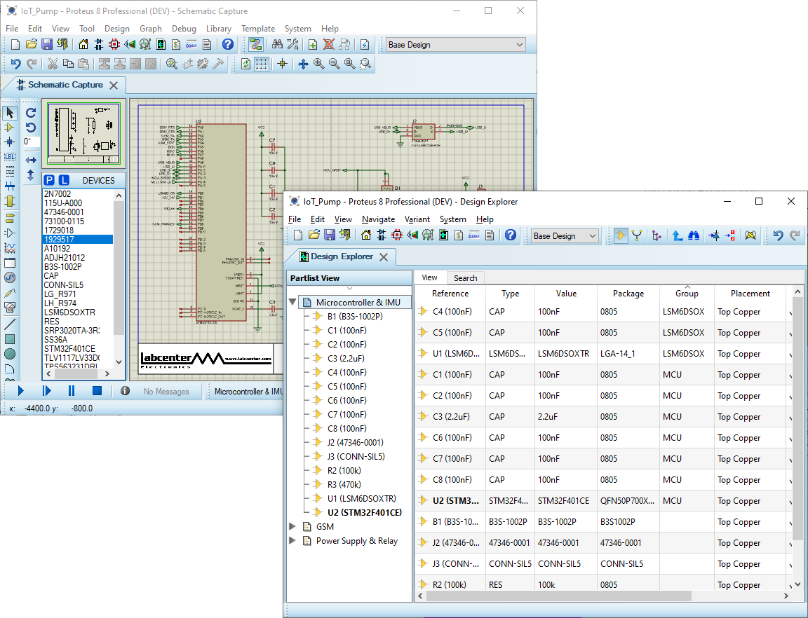
Split programs in Proteus
Alternatively, if you do prefer to work with tabs in a single frame you can quickly cycle between tabs using the standard Windows CTRL+TAB keyboard shortcut.
In its default mode, the Design Explorer looks a little like a typical file explorer. The left hand pane displays the sheets and the right hand pane displays the contents of the currently selected sheet. Clicking on another sheet in the left hand pane will result in the right hand pane showing the contents of that sheet.
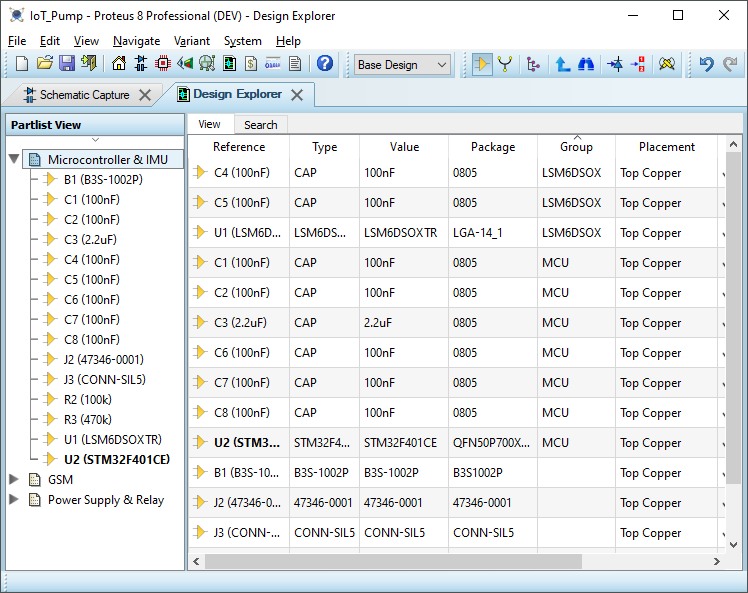
The Design Explorer
The Design Explorer has two distinct modes; partlist mode and netslist mode. The former will show a physical representation of the sheets (the components on a sheet) whilst the latter will show how the design is organized into groups of connections (nets). You can switch between the two modes via the Design Explorer Icons.

Design Explorer icon bar
Since we are in partslist mode by default let’s look at what we can do from there. You may remember that earlier in this tutorial we discussed how to check the packaging for a single part. The Design Explorer shows us the bigger picture and allows us to make a global check of the packagings on the design at a glance. All of the footprints used are displayed beside their schematic reference at the far right hand side of the right hand pane so all we need to do is scan down the list to make sure everything is packaged, switch sheets (via the left hand pane) and repeat the process. If a part on the schematic did not have a footprint assigned it would have bright red text stating 'MISSING' in this field to highlight the potential problem.
As all of the parts on our schematic are already packaged, we would need to deliberately mutilate the design in order to see this feature in action. If you would like to try this, then (in Design Explorer) find the LSM6DSOX (should be "U1") on the "Microcontroller & IMU" sheet and delete the text in its package field (would have been "LGA-14_1"). We can then go about fixing the problem we just created by right-clicking on the component and selecting "Show Schematic Part" from the context menu.
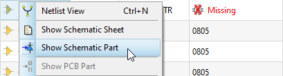
The Design Explorer's context menu
This will zoom the schematic around the part and tag it for editing. Simply right click on the highlighted part and select Edit Properties in the normal way. Now all we need to do is select the correct package from the dropdown again.
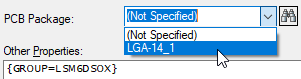
LGA-14_1 Assigned as the package
After making the change, the Design Explorer will live update to reflect the current status of the schematic.

Design Explorer showing the LSM6DSOX packaged again
We can also use the Design Explorer to investigate the connectivity of the schematic – for this we need to switch into netslist mode via the icon at the top left of the dialogue form. This will give us a view as shown below.

The Netlist icon
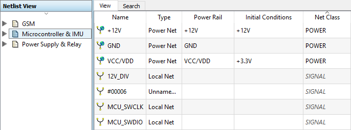
The Netlist view
The first point to note is the net names which, as we discussed earlier, are either named according to terminal or label or simply assigned a number if the net consists only of wire connections. We can right click on any net to view it’s connections on the current sheet by selecting the ‘Goto Schematic Net’ option from the resulting context menu. This is particularly useful when we want to check single pin nets for example, or if we want to name a net manually (see the section on connectivity considerations earlier in the tutorial). Finally, where we have a net or nets grouped with a named net class (far right column on the right hand pane) it can be useful to check our assignments.
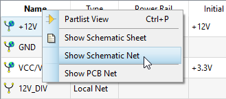
Goto Schematic Net will highlight the selected net
The Design Explorer is an extremely powerful tool and has many different uses throughout the lifecycle of a typical project. In particular it can be used as a link between the schematic and the PCB, facilitating cross-probing and PCB lookup. We recommend that you read and work through the chapter in the reference manual (Help Menu – Schematic Capture Help) for more information.
See Also
Design Explorer (Reference Manual).
Assembly Variants
Assembly Variants provide a simple method of managing multiple product configurations in a single schematic/PCB project. This is done by specifying the fitted or not fitted status of each component on a per variant basis. They are often used for excluding parts from cheaper versions of a product or for identifying PCB versions to firmware by controlling the use of pullup resistors on an MCU port.
In Proteus, Assembly Variants are configured primarily through the Design Explorer. Let's look at a simple example where we'll remove the GSM circuitry from a new product variant. Start by creating the new variant from inside the Design Explorer and naming it "NoVib".
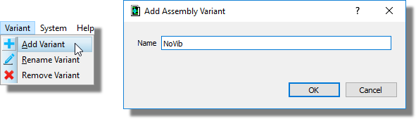
Notice that this gives us a new column in the component grid. Each entry currently has a tick which indicates that the part is fitted on the board for the variant. If we click on the entries for the budget column for the LSM6DSOX and it's two 100nF decoupling capacitors then they will change to a cross, indicating that these parts are to be excluded from the NoVib variant.
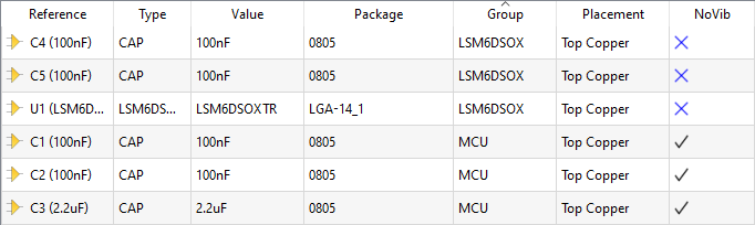
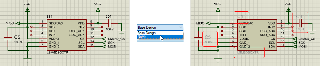
When you have more than one variant on the schematic you can switch between Active Variants via the variant combo box at the top of the screen. When we switch to NoVib variant you should see that the part reference for the IMU circuitry will be greyed out to indicate that the part is not present in the active variant.
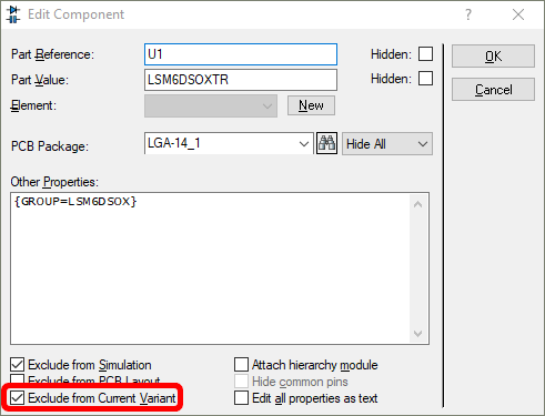
We could also have done this by individually editing the parts and checking the exclude from Active Variant box on the Edit Component Dialogue. You need to be very careful when working this way to ensure that you have first selected the variant you want from the combo-box at the top.
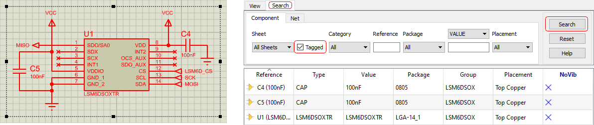
Note that you can quickly manage variants for a group of parts by first dragging a selection box around the parts and then showing selected in the search tab of the design explorer.
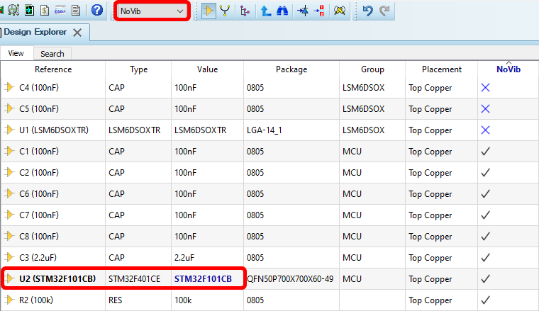
We can also change the value of components on a per-variant basis. Let's try this by assigning a slightly different (but pin-compatible) microcontroller to our NoVib variant. In Design Explorer, ensure that the "NoVib" variant is selected and that the "Microcontroller & IMU" sheet is selected. Then type a value of "STM32F101CB" under the Value column for the STM32 microcontroller.
The Proteus software manages the variant information through all of the output systems, changing the BOM Report, the Pick and Place files, the Assembly Drawings, the 3D Viewer and any export for MCAD to reflect the fitted status of the parts. Assembly variants do not affect the 2D PCB layout.
If you would like a little more practice, then try adding a "NoGSM" variant which does not contain any of the components on the GSM sheet.
You can add the @VARIANT text string to the schematic to indicate the current variant on the schematic. This is a useful reminder and particularly important for printing schematic documentation. See the header block in the schematic reference manual for more information.
See Also:
Assembly Variants (Reference Manual)
Header Block (Reference Manual)