MULTI-SHEET DESIGNS
Multi-Sheet Designs and Connectivity
For anything other than small designs it will usually be necessary to split the design into multiple sheets. This serves both to reduce clutter on the schematic and also to organize the design into logical blocks. The Proteus schematic capture fully supports multi-sheet designs and our tutorial design will indeed require 3 sheets ("Microcontroller & IMU", "GSM", and "Power Supply & Relay"), which will allow us to cover the relevant procedures. The work which we have done so far has been to complete the first sheet ("Microcontroller & IMU" circuitry), leaving us with the "GSM" and "Power Supply & Relay" sheets to be completed.
While beyond the scope of this tutorial it is worth mentioning that Project Clips provide a method for re-using logical blocks of design and layout. More detail is in the reference manual and a short tutorial movie is linked below.
Introduction to working with Project Clips
Also, note that what we are doing here is adding additional sheets at the same level as the first sheet. Proteus fully supports hierarchical designs where you use sub-circuits to contain logical blocks. This is discussed in detail in the reference manual.
See Also:
Multi Sheet Flat Designs (Reference Manual).
Sub-circuits (Reference Manual)
Project Clips (Reference Manual)
Practical Examples: Duplication of Design Hierarchies (Reference Manual)
Adding Sheets to a Design
To add a new sheet to the schematic we simply invoke the command from the Design menu as shown below.
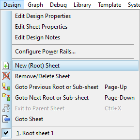
Creating a new sheet
Try this now to generate the second sheet.
Naming, Ordering and Navigating Sheets
Before we lay out the circuitry on this sheet we need to do a little housekeeping. While it’s not necessary it is often helpful to name the different sheets on the schematic and also to order them in some sensible fashion. We can do both of these things via the Edit Sheet Properties command on the Design Menu.
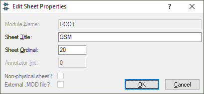
The Edit Sheet Properties dialogue form
The Sheet Title is what will be displayed and should therefore reflect the contents of the sheet. In our case let’s name it ‘GSM’.
Sheets on the schematic are organized by Sheet Ordinal and by default these are 10, 20 and so on. A sheet with an Ordinal of 20 will therefore appear behind the first sheet (default Ordinal 10). If you prefer purely numeric nomenclature we can change the sheet name to be ‘2’, to better reflect it’s position in the design structure.
Note that there is also a Master Sheet, present in all designs, which allows the application of a company logo, revision number, author and other schematic information. Use of the Master Sheet is beyond the scope of this tutorial, but more information can be found in the Templates chapter of the accompanying reference manual (Help Menu –> Schematic Capture Help).
See Also:
For completeness we should also follow this process for the sheet we have just finished laying out. Before we can change the properties of a sheet we must first navigate to that sheet in the design and Proteus provides several ways to do this :
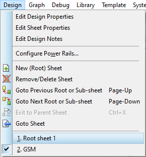
- From the Design Menu select Root Sheet 1 at the bottom of the menu,
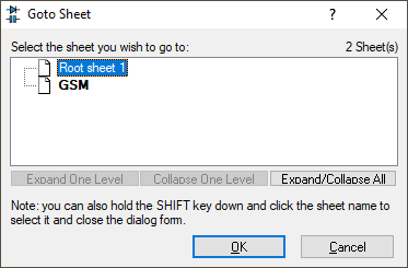
- From the Design Menu, select the Goto Sheet command, select the sheet and click OK to switch to that sheet.
- Use the PGUP and PGDOWN keyboard shortcuts to navigate between sheets. These cycle up and down the sheets respectively (although for a currently two sheet design they will seem to have the same function!).
The Design Explorer is also a powerful way to navigate the schematic – this is covered in the Design Verification section of the tutorial and in more depth in the reference manual.
Once you find yourself back on the sheet we have laid out simply repeat the process above, with a sheet title of ‘Microcontroller & IMU’.
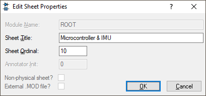
Sheet 1 properties
Our design will require one more sheet (three in total), so add another sheet titled 'Power Supply & Relay'. Once done, you should now see correctly organized and labelled sheets at the bottom of the Design Menu
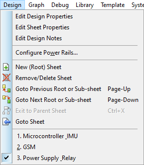
This is what you should see in the Design menu
Connectivity between Sheets
Now that we have taken care of the naming, we need to lay out the circuitry for the remaining two sheets. The "Relay & Power" sheet is arguably the more interesting of the two to draw, so make sure that you are currently on that sheet and then let's look at the circuitry. The following screenshot shows the circuit we need to draw.
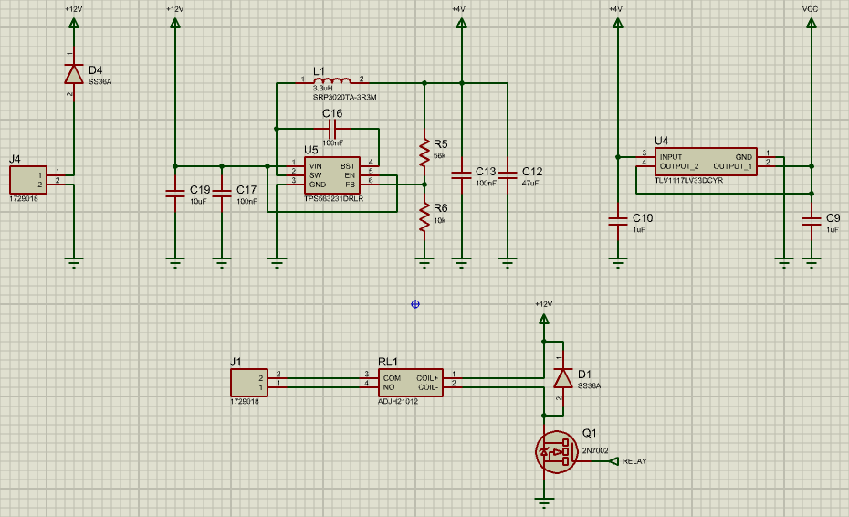
Power Supply & Relay Sheet
There are four logical blocks of circuitry; power input, a DC-DC buck converter, a 3.3V regulator, and a power relay.
If you feel that you need more practice then you can use all of the techniques we have covered so far to complete the schematic. Alternatively, if you are comfortable with the basics of schematic entry then we will load a pre-supplied completed schematic in the next section. Regardless, there are a couple of points of note that are worth emphasizing.
Firstly, connectivity between sheets is achieved by having terminals with the same name on both sheets. From the screenshot above we can see the "RELAY" control signal terminal, which connects to the microcontroller on the first sheet; as well as various power supply terminals. Terminals thus allow signals to propagate not only across a sheet but also across sheets.
See Also:
Secondly, it is possible when placing wires to ‘guide’ the wire placement as you place the wire. This is achieved by left clicking the mouse as you change direction, which places an ‘anchor’ to help the follow-me algorithm place the wire the way you want. Typically, this is useful on more complex wire trails but we can look at a simple example for the purposes of illustration.
Consider the connection between the power input and the enable pins of U5.
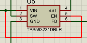
Wire between VIN and EN on DC-DC converter
If we delete this wire (right click and select delete), we could replace the connection in the usual way and the follow-me algorithm would make a decent job of it. However, if we wanted to be more precise we could proceed as follows:
- Hover the mouse over the EN pin such that it turns green and then left click to start wire placement.
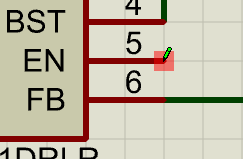
- Move the mouse along to the right and then left click the mouse once to place an ‘anchor’.
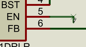
- Move the mouse down, left click to place an anchor, then left, left click to place an ‘anchor’ and finally up onto the wire between the VIN pin and capacitor.
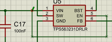
This technique constrains the follow-me algorithm and provides greater control during wire placement. If at any time during placement you change your mind and wish to remove an anchor simple right click the mouse once. Finally, if you want to completely disable the wire-auto-router and, for example, place a wire at 45 degrees, simply hold the CTRL button down on your keyboard during placement.
The "GSM" sheet (shown below) is the final sheet to be completed, and contains many examples of signal terminal connections (for connections both on the same sheet as well as to the microcontroller sheet). As before, if you feel that the practice will be beneficial then you can draw the sheet out, otherwise if you feel that you are already comfortable with schematic entry then we will load a pre-supplied completed schematic in the next section.
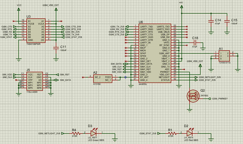
GSM Sheet
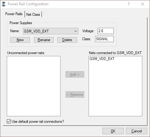
Note that the GSM sheet contains power terminals for a new net - "GSM_VDD_EXT". This net needs to be manually configured in the Power Rail Configuration dialogue, so open the dialogue by selecting "Configure Power Rails..." from the Design menu. You should now see "GSM_VDD_EXT" listed under "Unconnected power nets"; we need to create a new power rail for this net, so click "New" and enter "GSM_VDD_EXT" for the name (note that the power rail name does not need to be the same as the net name, although we are choosing to give them both the same name in this case). Once the new power rail has been created, add the unconnected GSM_VDD_EXT net to it by selecting the unconnected net and clicking "Add". Enter a voltage of 2.8 for this net, and assign it to the SIGNAL class (this is not a high-current net, the GSM module can only supply a maximum of 50mA to it).
Power Rail Configuration for GSM_VDD_EXT rail / net