SUPPLIED REPORTS
Introduction
Several report types are supplied by default to provide skeleton templates for common documentation or design auditing tasks. These are discussed in turn below.
Engineering Change Order
This is an example structure for an engineering change. Depending on requirements and/or preferences this can be as simple as a list of changes (revision history) a semi-formal report for a single planned revision as outlined below or a highly specific process.
Design Rule Report
This document lists the design rules in force on the layout, together with their clearances. It does not indicate which rules apply or have precedence in a given situation.
The tree view in the design rule manager itself will show you all rules in force in a given region.
See Also:
Length Matching Report
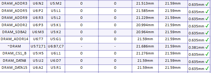
This document contains information on all length matched routes on the PCB.
See Also:
Differential Pairs Report
This report produces information about each differential pair on the board, along with specified tolerances and a compliance status.
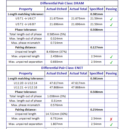
Example Differential Pair Report
See Also:
PCB Manufacturing Document
This document contains information on the construction of the PCB and can be sent to the board manufacturer along with the Gerber files as a reference document. It includes board stackup information, drill tables, assembly drawings, fiducial positions and PCB artwork amongst others.
See Also:
PCB Specification Document
This is a formal skeleton template for a PCB Specification that you might populate and provide to your PCB manufacturer. It lists fabrication requirements, quality standards, testing procedures and specifications for different stages of the PCB manufacture process.
See Also:
Single Pin Net Report
This document contains information on single pin nets in the current project. A single pin net is defined - unsurprisingly - as a pin with no connection. To use this report as a QA tool the process would be:
- Generate the report.
- Use Design Explorer to locate the pins.
- Either add an NC terminal to mark the pin as NC or wire the pin if it has accidentally been missed.
- Right click to regenerate the report then repeat as needed.
- You should see no single pins at the end of the process.
See Also:
Variant Comparison Report
This document contains information on the differences between assembly variants used in the current project. Variants are listed along with the fitted or alternate part configuration of every part that deviates from Base Design in that variant.
See Also:
Component Placement Report
This document contains information on the placement of each component on the schematic. It is intended for use during project review.
In order to work properly the schematic will need to have been created from one of the Labcenter pre-supplied design templates so that the grid references are present on the sheet borders. If you prefer, you can add grid markers to your own templates and then generate the report.
See Also
TestPoint Report
This document contains information on the location of all testpoints on the board. It is intended for use during project review. The report is split into 3 sections.
- Testpoint listing. Shows the size, co-ordinate position and layer of all the testpoints along with a connected status.
- Testpoint count. Shows the number of testpoints per net, grouped by net and compares the number with any specified minimum number.
- Testpoint plot. Shows an image (or images) with location of testpoints on the top / bottom of the board.