PRINTER OUTPUT
Overview
Output through standard Windows device drivers is performed using the Print Design command on the File menu. The command opens the Print Design dialogue form, from which you choose the printer, what is to be printed, the scaling, the page orientation and the position of the output on the paper. Context sensitive help is available on all fields within the dialogue form.
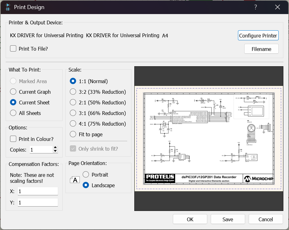
The Print Design dialogue form with the preview area on the right hand side
Specifying a Printer Device
The printer is selected inside the Print Design dialogue form itself. The Printer & Output Device group at the top of the form shows the current printer name, its type and the paper it is set to use; press the Configure Printer button to open the Print Setup dialogue form, where you can change the device, the paper size and the paper orientation, or reach the driver's own settings. Your choice is remembered for future sessions.
What to Print
The What To Print group selects the part of the design that is sent to the printer. Five options are offered and only those that make sense for the current design are enabled, which is why you will often find some of them greyed out:
- Marked Area, the rectangle set with the Mark Output Area command on the File menu. Enabled only when a marked area exists.
- Current Graph, the maximised graph. Enabled only when a graph has been maximised.
- Current Sheet, the sheet you are looking at. Always available while you are editing a schematic.
- All Sheets, every root sheet and hierarchical sub-sheet of the current design, one page per sheet.
- All Board Sheets, the same for every board in the project. Enabled only for a multi-board project.
Where a graph has been maximised, Current Graph is the only option offered, since the other four apply to the schematic rather than to the graph.
Scaling
The Scale group prints at 1:1, or at one of four standard reductions: 3:2, 2:1, 3:1 and 4:1, described on the form as 33%, 50%, 66% and 75% reductions respectively. The remaining option, Fit to page, sizes the output to the paper instead.
Where the output area is larger than the printable area both dimensions are examined and the X and Y dimensions are shrunk together according to the dimension with the largest offset, which ensures that the whole of the output area falls within the printable area. Where the output area is smaller than the printable area both dimensions are expanded together according to the dimension with the smallest offset, again keeping the result inside the printable area.
Only shrink to fit? is enabled when Fit to page is selected and is ticked by default, in which case a large drawing is reduced to fit but a small one is left at its natural size. Clear it if you also want small drawings enlarged to fill the paper.
Compensation Factors
The Compensation Factors group carries separate X and Y values, both 1 by default, which stretch or shrink the output very slightly to compensate for the behaviour of a particular device.
The compensation factors are not scaling factors, and the dialogue form says so on its face. Use the Scale group if you want to print the drawing larger or smaller; use compensation only to correct a measured dimensional error in the finished output.
Colour, Copies and Orientation
Tick Print in Colour? in the Options group to print with the colours you see on screen. When it is clear, every colour is forced to black and object filling is suppressed, which is what you want for a plain drawing office print. Copies, alongside it, sets the number of copies to be printed and accepts any figure from 1 to 999.
Page Orientation switches the paper between Portrait and Landscape. The icon beside the two buttons and the preview both follow your choice immediately.
Print Preview
The print preview appears on the far right of the Print Design dialogue form and shows the position and size of the drawing relative to the paper. It updates live as you configure the dialogue form, so the effect of a change to the scaling, the colour setting or the page orientation is visible immediately.
The preview is disabled when All Sheets or All Board Sheets is selected and the sheets of the design are not all the same size, because there is then no single page layout to show. A warning is displayed when the selected scope spans sheets of different sizes. If all the sheets are the same size the preview stays available.
Positioning the Output
You can adjust the position of the printed area by left depressing the mouse on the print preview and dragging the drawing to the desired position. Alternatively, right click on the preview and choose one of the five preset positions from the context menu: Position at Center, Position Top Left, Position Top Right, Position Bottom Right or Position Bottom Left.
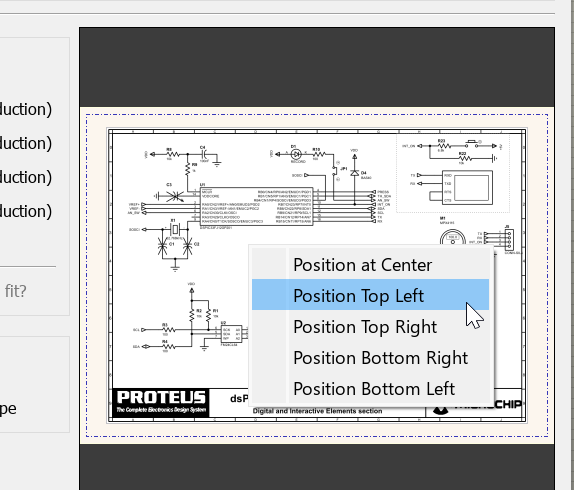
The context menu for positioning, launched by right clicking on the preview area
Positioning is proportional rather than absolute, and the output is always kept inside the printable area reported by the printer driver, so it cannot be dragged off the edge of the paper.
Changing the scale or the page orientation re-centres the drawing on the page, so set those first and position the output afterwards.
Printing to a File
Tick Print To File? if you want the printer driver to write its output to a file rather than send it to the device, then press the Filename button to choose where the file is written. This is occasionally useful for submitting a job to a bureau that works from printer files.
Plotters
A plotter attached through a Windows driver is printed to in exactly the same way as any other device, by selecting it in the Print Setup dialogue form and printing from Print Design. Output to a pen plotter is monochrome whatever the state of Print in Colour?, because a single pen is selected for the whole plot.
Where you print several sheets to a pen plotter, you are prompted between one sheet and the next so that you can change the paper. The prompt asks whether the next sheet is ready and offers READY to continue or CANCEL to abandon the rest of the job.
For a plotter that you drive from a file rather than through a Windows driver, use the Export Vector File command, on the Export Graphics submenu of the File menu, which writes HPGL, HPGL (CTO), HI-80 or DPML directly.
Repeatable Print Runs
Printing from this dialogue form is a manual operation, so a set of prints that you produce at every revision has to be set up by hand each time. For a single print job, the Save button beside OK stores the current settings without starting the print, so the dialogue opens with the same configuration already in place next time. Where you need to run a whole set of print or export tasks in one operation, use the Output Job Manager instead. An output job profile stores the settings for each print or export task, including Schematic PDF, and runs the whole set together.
See Also: