BUS CONNECTIVITY RULES
The Base Alignment Rule
The Proteus schematic supports bus pins and wiring between bus pins. In the main, this operates intuitively, but it is necessary to be aware of the behaviour of Proteus in some of the more subtle cases that can arise with this feature.
Within the netlist compiler, all bus entities (pins, terminals and module ports) are assigned a bus range. This is held internally in terms of a base and width so the bus D[0..7] has a base of 0 and a width of 8.
The fundamental basis for bus connectivity is that all entities on a bus (except for bus labels around a junction dot) are connected by Base Alignment. This means that, for example, if two bus pins D[0..3] and Q[4..7] are connected by an unlabelled bus wire, then D0 will be connected to Q4, D1 to Q5 and so on.
The base alignment rule applies, even if the bus pins being connected are different segments of the same bus. For example, the diagram below will be interpreted as making a 4 bit bus which connects Q0 to Q4 to D0 to D4 and Q1 to Q5 to D1 to D5 and so on.
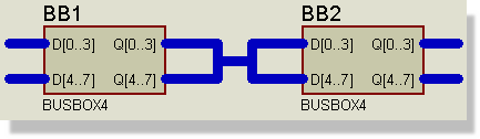
4 bit bus with the base alignment rule
If this is not what is required, then you must use bus labels to designate the required connectivity as explained in the next section.
Using Bus Labels to Change the Connectivity Rule
The only exception to the Base Alignment Rule is in the situation where several labelled bus sections are combined at a bus junction dot. In this case, the bus sections are combined on a Like Bit basis.
The following example shows how some bus pins can be cross-connected using bus labels:
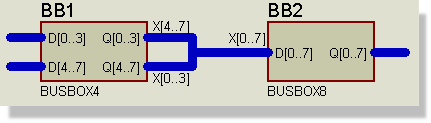
Bus pins cross-connected
In this case, Q0 connects to D4, Q1 to D5, Q4 to D0, Q5 to D1 and so on. It is worth emphasising here that the choice of name stem for the bus labels is completely unconnected with the names of the bus pins. You could have used D[0..3] etc. but it would make no difference whatsoever to the connectivity.
It is also worth re-emphasising that the Base Alignment Rule applies in all cases except bus labels at a junction dot, so that the connection between Q[0..3] and X[4..7] connects Q0 to X4 and so on.
Using Bus Terminals to Interconnect Buses
As with ordinary wires, it is possible to connect sections of bus without actually drawing in bus wiring. This can be achieved using bus labels and/or bus terminals as shown below:
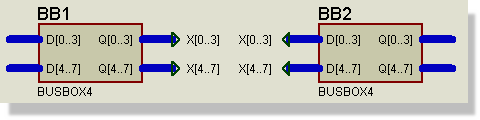
Terminals on buses
If you omit the range specifier of a bus terminal or label, then it will take its range from the bus section to which it connects. The bus range is determined as follows:
- If there are bus labels present in the section, then these are combined on a like bit basis so that the meeting of X[0..3] and X[4..7] at a dot creates a range at the dot of X[0..7]. X[4..7] meeting X[8..11] would create a combined range of X[4..11].
- If there are no bus labels in a section, then the base of its range is 0 (since pins are always base aligned) and the width is that of the widest pin. To put this another way, an unlabelled bus section is always deemed to have a base of 0, irrespective of the ranges of the pins that connect to it.
The latter point does carry the potential to trap the unwary. Consider the diagram below:
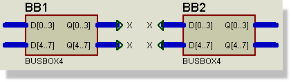
Joining bus pins together
Since the X terminals all get ranged as X[0..3], the diagram in fact connects all four bus pins together on a 4 bit bus, rather than creating an 8 bit bus between Q and D. The moral of this is to use explicitly ranged bus terminal labels in all but the simplest cases and always if you are in any doubt.
Note that an isolated section of bus wiring in which there are no bus pins, and in which none of the labels or terminals carries a bus range, is not allowed since Proteus cannot then determine the names and number of individual bits to be interconnected. Instead, you should use a scheme such as the one shown below:

An isolated bus section needs an explicitly ranged terminal at each end
Failure to do this will result in a netlist compiler error.
Connections to Individual Bits
In most circuits, even where all the major ICs use bus pins, it becomes necessary to connect to individual bits of a bus. To do this, you need to know about the net names that Proteus generates when it encounters a bus label or terminal. You should by now appreciate that when the netlist compiler encounters an ordinary Logical Terminal, or a Wire Label, the object donates a net name to the partial net. All partial nets which have one or more net names in common are then taken to be connected.
When a bus label or terminal is encountered, it generates a set of net names, which are assigned to the partial nets that constitute each bit of the bus. The bus label D[0..7] thus generates the net names D0, D1 ... D7.
In the circuit, both the NAND gate and the 74154 are connected to Q[0..3] by this mechanism.
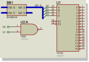
Notice that the bus is not tapped
There are several things to note from this example:
- Connections to the bus bits can be made without actually drawing a wire coming out of the bus. The bus label Q[0..3] gives the bus bits the net names Q0-Q3 and these can then be referred to and connected up in the usual way.
- The bus label Q[0..3] is mandatory. The bus pin Q[0..3] does not contribute any net names as this could lead to unwanted connectivity if there were several like named pins on the design. This behaviour is also consistent with the behaviour of ordinary, non-bus pins which do not donate net names either.
- In fact, the junction between a wire and a bus has no significance at all, as far as Proteus is concerned.
- In the above circuit, you could just label the bus as Q, since the bus pin Q[0..3] will contribute the range information.
Tapping a Large Bus
A not uncommon situation that arises in the use of buses is that of the need to break a large bus into several smaller buses which connect to chips which are perhaps 4 or 8 bits wide.
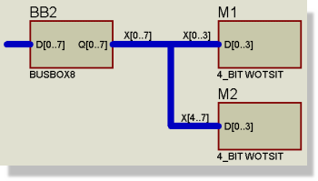
An 8 bit bus split into two 4 bit buses feeding sub-circuit modules
Here, the 8 bit Q output of the BUSBOX8 is split into two four bit buses which are then fed into the 4_BIT_WOTSIT sub-circuit modules. The Base Alignment Rule applies at the connection of X[4..7] to D[0..3] to give the desired result. The label X[0..7] is actually redundant in this case but it does no harm to be explicit.
This diagram also shows how bus connectivity can be combined with hierarchical design to give a very powerful scheme for representing array like circuitry. The module ports behave in the same way as pins for bus connectivity purposes.
Some Simple Examples
The first example is a simple connection between A and B. This connects A[0] to B[0], A[1] to B[1] etc. The bus does not need a label as it is not tapped.
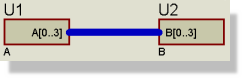
A simple untapped connection between the A and B bus pins
In the next example the bus is not labelled. The bus doesn't get a name automatically (would it be A[0..3] or B[0..3] ?) and so the resistor is not connected to the bus. This is a common mistake when tapping buses: remember that the bus itself must be labelled.
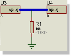
With no bus label, the resistor is not connected to the bus
What we want instead is something like the screenshot below. In this case the bus has a label, X[4..7], so A[0] connects to [X4] connects to B[0], A[1] connects to X[5] connects to B[1] etc. The resistor connects to X4 and thus also to A0 and B0.
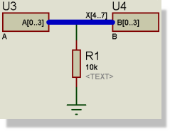
Labelling the bus X[4..7] connects the resistor to X4
The example below connects A[0] to B[0] to C[3], A[1] to B[1] to C[4] etc. (remember the Base Alignment Rule). C[7] to C[10] are not connected and again, as nothing is tapped, no bus label is required.
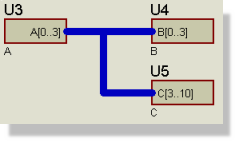
A base aligned connection between the A, B and C bus pins
The final example is a little more involved.
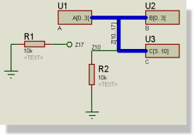
A labelled bus tapped at Z10 and Z17
This connects as follows :
A[0] to B[0] to C[3] to Z10
A[1] to B[1] to C[4] to Z11
A[2] to B[2] to C[5] to Z12
A[3] to B[3] to C[6] to Z13
C[7] to Z14
C[8] to Z15
C[9] to Z16
C[10] to Z17
The resistor R2 is connected to Z10 and therefore to A[0], B[0] and C[3].
The resistor R1 is connected to a terminal labelled Z17 and therefore connects to net Z17 which is C[10] on part U12.
General Comment and Warning
The preceding sections describe the behaviour of bus pins and labels in the contexts that we envisage them being used. Clearly, other possibilities may be drawn and the hope is that the explanations of how bus pins work will enable you to perceive what will happen.
However, if you are in any doubt whatsoever as to what connectivity will result from what you have drawn, we strongly recommend that you check the resulting netlist in the Design Explorer before simply assuming that what you have drawn will result in the connectivity that you expect.
This said, you will not easily go wrong if you remember the following two points:
- The Base Alignment Rule always applies, except for the case of labelled bus sections being merged at a bus junction dot.
- Use un-ranged bus terminal labels only in simple cases; an unlabelled bus terminal or module port will take a base of 0 if there are no other bus labels in the bus section.
See Also: