DESIGN OVERVIEW
Introduction
The circuit we are going to draw is shown below. This is reasonably straightforward schematic that will nonetheless allow us to cover most of the major features of the schematic capture package. Being a real-world design, it will also allow users to follow the design through the PCB phase of development via the PCB tutorial.
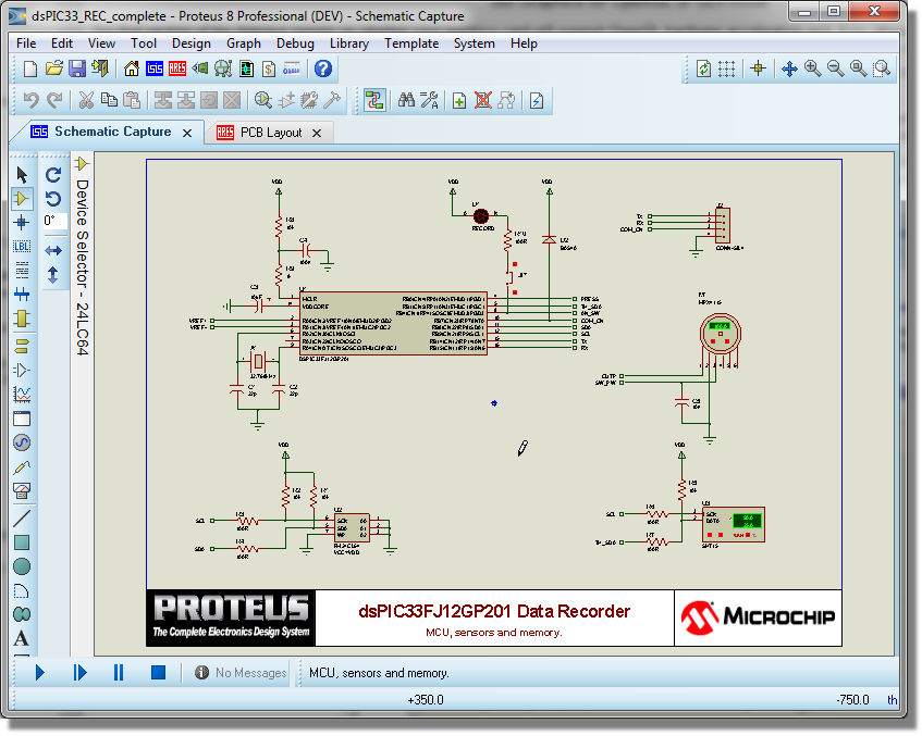
The dsPIC33 Data Recorder Sample Design
Two things about the way the drawing is arranged are worth noting now, because they shape everything we do from here on. The design is spread across two sheets, with the processor, sensors and memory on the first and the analog, reference and power circuitry on the second. Within each sheet the circuitry is split into logical blocks, one function to a block. That is partly aesthetic, but it also keeps wiring clutter down and it gives us a natural excuse to use terminals rather than long wires for the connections between blocks.
General Description
The dsPIC33 Data Recorder Tutorial circuit is a solid state recorder designed to collect three of the most important environmental variables:
- Atmospheric pressure
- Ambient temperature
- Relative humidity
A number of low cost silicon transducers with built-in signal conditioning or digital interfaces have been used for measurement. This reduces the number of components to the minimum required for dsPIC33 interfacing.
All measurements get periodically stored into a non-volatile, low power memory in raw binary format for later transfer to a host PC either by using a serial terminal or, more properly, a simple program (not supplied with the project). For the purpose of this project a serial terminal is used.
The circuit is designed to work with a battery for relatively long period in an unattended environment and, as such, a particular emphasis has been given to optimising the power consumption and consequently the battery life. The recorder will sleep most of the time and will be woken up periodically only to accomplish the required recording operations.
Circuit Description
The following is a block diagram showing the behaviour and interaction of the circuit components.
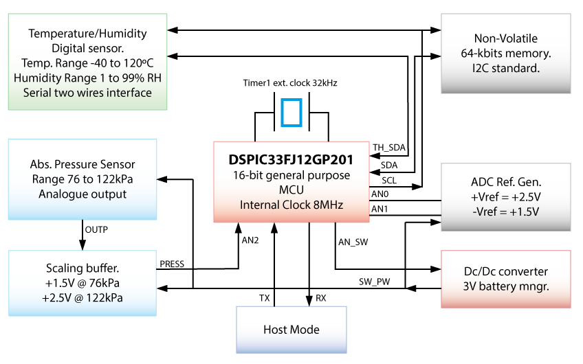
Block diagram of the dsPIC33 Data Recorder Design
We’ll cover the basics of the design construction as we progress through the tutorial but in order to keep the focus on the practical aspects of using the software, design decisions and theory will not be discussed in this document.
If you would like the theory anyway, and you have configured the AI assistant, you can simply ask for it. With one of the pre-supplied sample projects open (or with your own drawing far enough along), open the chat side bar using the ProPilot (AI Assistant) command on the Help menu and ask something like "explain what U4 does in this schematic". Because ProPilot can see the design you have open, it answers for this circuit rather than in general terms. Treat the reply as a knowledgeable second opinion rather than as gospel, and challenge it if something looks wrong.
See Also: