ARDUINO HARDWARE
Introduction
Designing 'virtual hardware' for your project is greatly simplified in Visual Designer. The various options available to you are described in detail below.
Arduino Base Board
In hardware, Arduino is a system consisting of a fairly simple base board with an AVR microcontroller, some supporting electronics and Arduino pin headers (connectors). There are then a wealth of peripheral boards (shields) which plug into the pin headers to form the hardware for a particular project.
In Visual Designer for Arduino, the creation of the project is the point at which you make your decision on the base board (E.g. Arduino Uno, Arduino Mega). This is automatically placed on the schematic when the project is created.
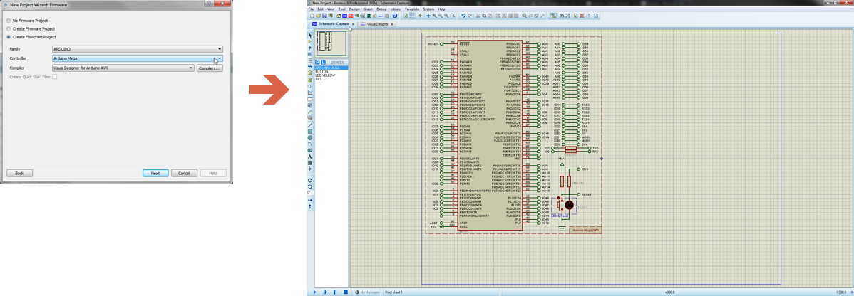
Automatic placement of the Arduino Mega on the Schematic when the Project is created.
Arduino Shields
Arduino shields are modular circuit boards that piggyback onto your Arduino base-board to instill it with extra functionality. They are the simplest way to add hardware functionality to your project because the circuitry and connectivity on the schematic happens automatically.
Adding a Shield
When you then want to add a shield in Visual Designer you right click on the Project Tree and select 'Add Peripheral' from the resulting context menu. Select the 'Adafruit' category on the peripheral browser and then select the shield you want to add. This will auto-place the shield electronics on the schematic.
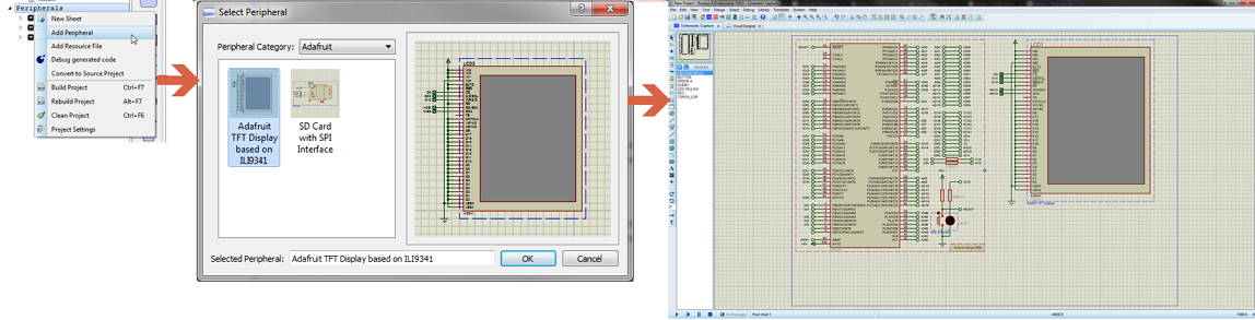
Adding a Peripheral will auto-place and auto-connect on the schematic.
Writing a Program to Control a Shield
Shields appear in the project tree in Visual Designer once picked from the Peripheral Gallery. They include high level methods that allow you to quickly control the connected electronics via flowchart blocks.
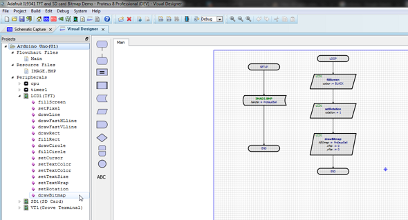
Drag and Drop methods make it simple to drive the shields.
Potential Pitfalls
Working with Viirtual Shields is the simplest method to quickly create projects in Visual Designer. You do however still have to take care with what hardware you choose to use. For example:
- You need to make sure that your use of Arduino shields is compatible with hardware. For example, some shields are incompatible because they make use of the same resource on the CPU (e.g. Timer1). Others are pin incompatible.
- You need to make sure that your target Arduino base board has enough memory to handle the shields you are adding to it. In particular, with an Arduino Uno you can run out of memory if you add shields with large and complex software stacks.
Grove Sensors and Modules
Grove is a modular electronic platform for quick prototyping. Every module has one function, such as touch sensing, creating audio effect and so on. You simply plug the modules you need into the base shield and then connect the base shield to the Arduino base board in the normal way.
The Grove Starter Kit Plus is a great way for beginners and students to get started with Arduino. The Grove Base Shield drops onto your existing Arduino and lets you connect up to 16 Grove modules without any fuss. The Arduino headers are still broken out on the top of the shield making it very easy to connect other breakout boards and sensors to your Arduino.
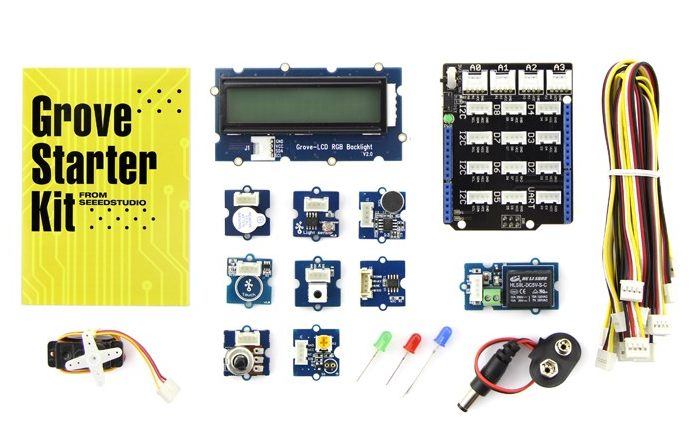
Grove Starter Kit Hardware.
Adding a Grove Module
You can add a Grove module in the same way as adding a shield, except that you select the Grove category in the Peripheral browser.
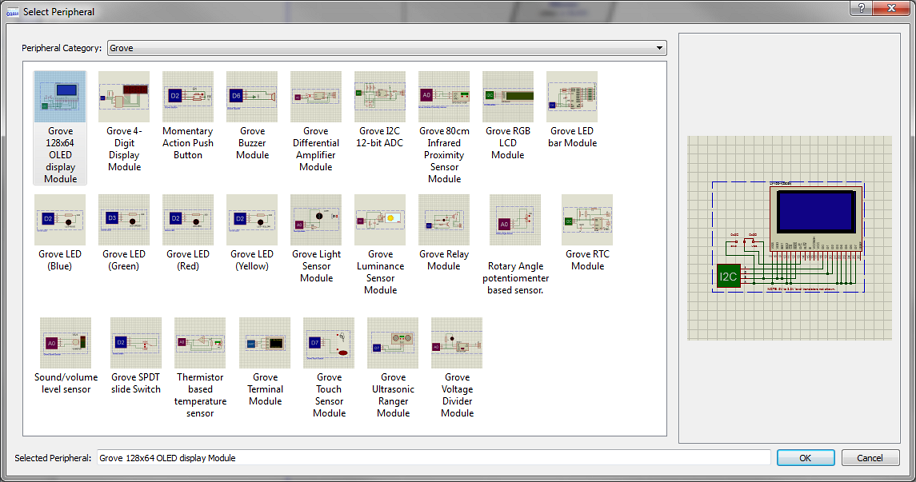
Adding Grove Starter Kit modules in Visual Designer.
You can then control the Grove peripherals via the high level methods available from the Project Tree. Multiple peripherals and sensors can easily be added to a single project which provides an extra level of flexibility over using standard Arduino shields.
Potential Pitfalls
When you are working with Grove modules in Visual Designer the process is identical to working with complete Arduino shields. However, since the modules themselves plug into an Arduino shield, you need to take care not to re-use a connector on the Grove board. The real Grove base-board shield will look something like the following:
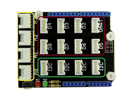
Grove Shield - the sensor modules plug-in to the exposed header pins.
When you add a Grove peripheral it will be assigned an ID on the schematic corresponding to a connector on the real board. If you get a duplicate, you'll need to edit and rename one of the connectors to a free slot.

If two grove modules have the same connector, you need to edit one and assign to an unused header slot on the Grove Shield.
You need to make sure that your use of Grove modules is compatible with hardware. Since the pins used in each socket overlap it is quite easy to mistakenly use the same pin twice. A good example of this is discussed in Tutorial 2
Breakout Boards and Peripherals
The third category of hardware that you will find in the Peripheral Gallery is breakout boards. These are useful and interesting pieces of electronics (often single components) for which we have provided control methods inside Visual Designer. So, when you add a breakout peripheral to your project, you can drive it from the methods it adds to the Project Tree.
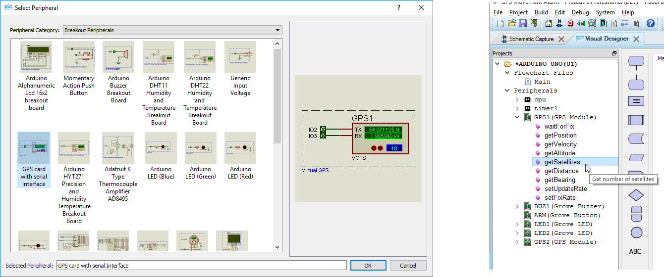
Breakout boards provide even more flexibility on the schematic. Indeed, they often connect to other schematic components that you want to place and wire yourself.
Potential Pitfalls
CPU resources and pin assignments need careful consideration.
Schematic Design
With Visual Designer you have access to the full power of the Proteus VSM simulation environment. This means that you have a professional schematic capture tool with tens of thousands of embedded components that you can place, wire and simulate.
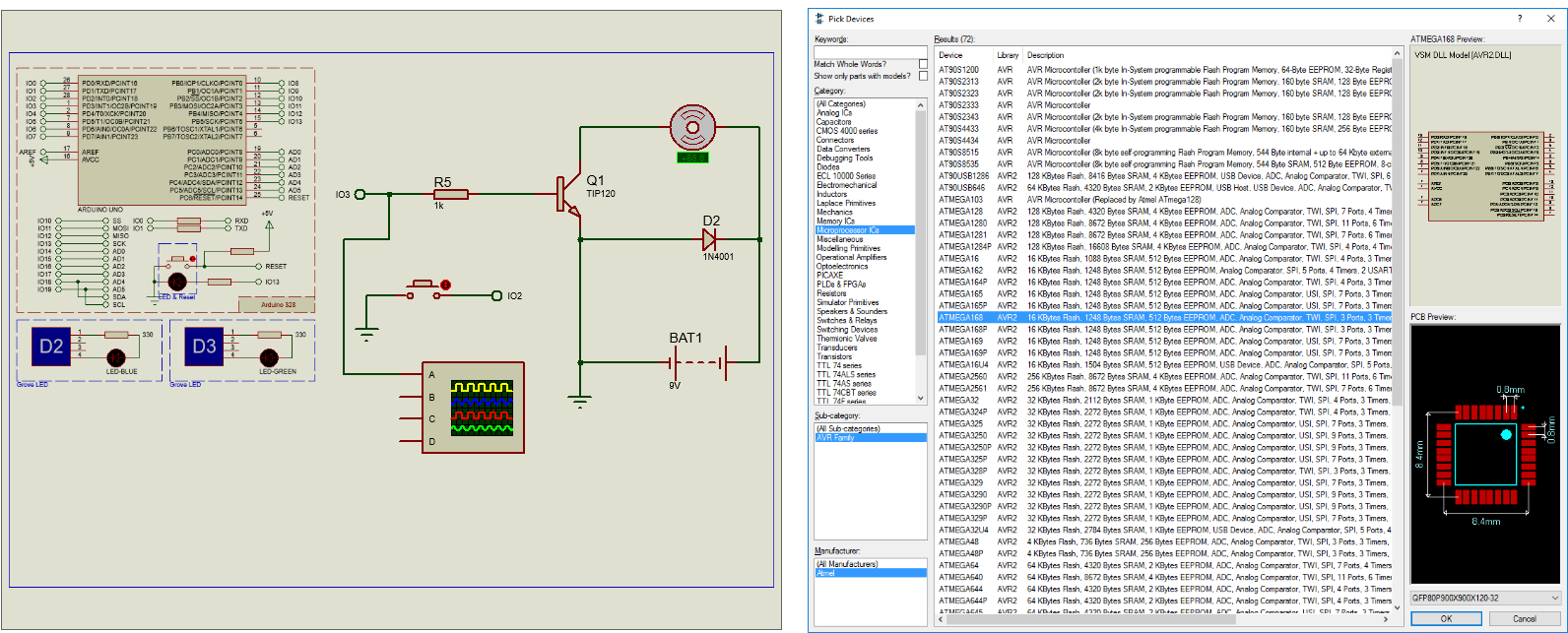
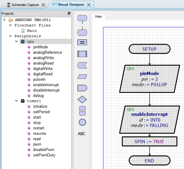
This is the most flexible design method of all but involves a significantly higher learning curve. The programming in Visual Designer will have to be done via the CPU methods rather than specific methods for peripherals.
See Also :
Tutorial 5: Introducing Schematic Design
Potential Pitfalls
Schematic design for simulation is a large and relatively complex topic. In addition to the basic of placement and connectivity there will also be power considerations and you will need to program for interconnect protocols where appropriate. At this stage, the transition from Visual Designer to Proteus VSM should be considered as there is a point beyond which C programming is required to effectively design the embedded system.