TUTORIAL 2: LUX SENSOR
Introduction
In this tutorial we are going to use a couple of Grove sensors and an LED to design a mini nightlight. Project setup is covered in the first tutorial so we'll assume that you have a blank Arduino Uno project in front of you.
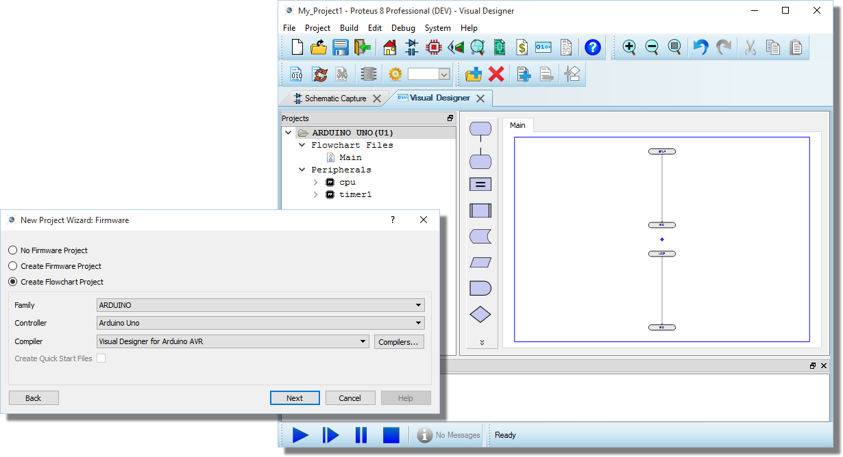
This tutorial is also covered by a short movie on the Labcenter Youtube Channel
Adding Hardware
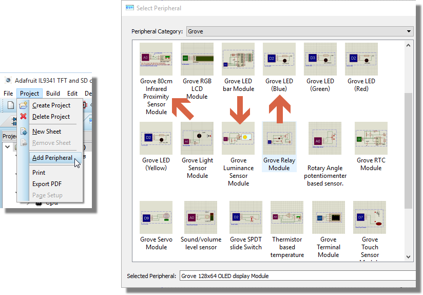
We'll use the Grove infra-red proximity sensor and the Grove luminance sensor along with a Grove LED. All of these can be picked via the Add Peripheral command on the Project Menu.
After they have been added to the project, you will see the methods for controlling the peripherals in the Project Tree and the 'virtual hardware' for the peripherals placed for you on the schematic.
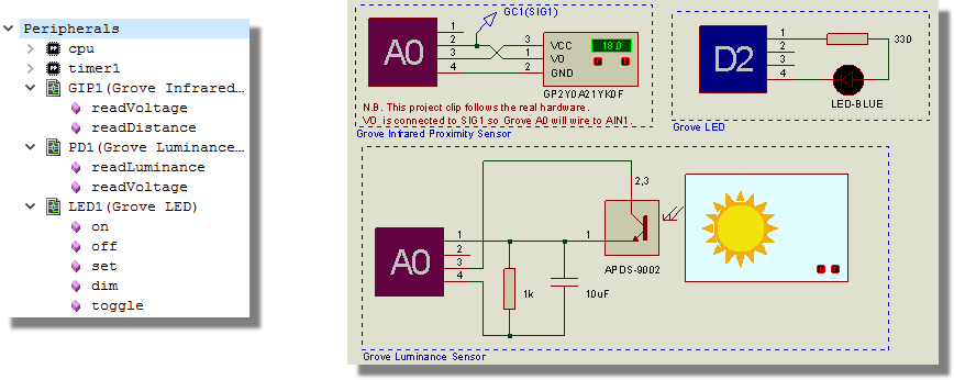
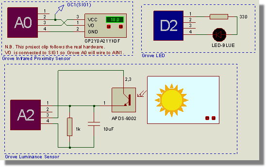
Note that the connectors are both labeled A0 and will need to be manually changed to be A0 & A2.
It is vitally important to configure the Grove connectors properly and this is often not as simple as it first appears. Let's take an example:
The real proximity sensor requires only three wires with the fourth left NC. Note therefore that, when plugged into socket A0 the sensor is connecting to analog pin A1.
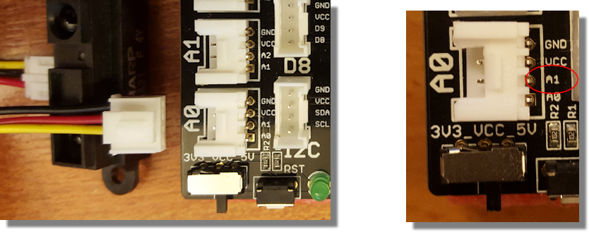
This is fine, except if you then plug the luminance sensor into socket A1. The luminance sensor will use analog pin A1 on socket A1 and therefore clash. You should plug this sensor into socket A2.
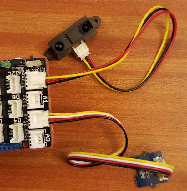
Golden Rule
Look closely at the Grove board to see the connections and double check against the sensors for conflicts.
The sockets include connections through to two Arduino IO pins and there is a pin overlap. For example:
- Socket A0 can use pins A0 and A1
- Socket A1 can use pins A1 and A2
- Socket A2 can use pins A2 and A3.
- etc.
Digital sockets are exactly the same.
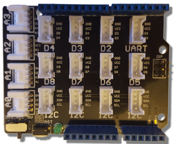
Our configuration for this project is therefore proximity sensor in socket A0 and luminance sensor in socket A2. The LED can be in any digital socket we like.
Designing the Program
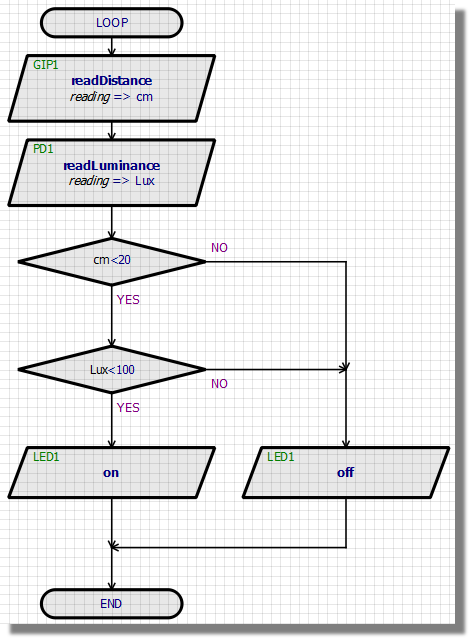
In our nightlight mock up we are looking for our LED to light when the following are true:
- It's is dark.
- Someone is nearby.
These are both decisions on the flowchart. Start by drag and drop the readLuminance() method onto the loop routine of the chart.
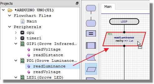
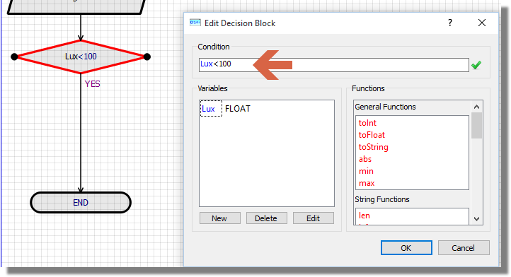
This sensor returns a lux value between 0 and 1000, with 0 being pitch black and 1000 max light. Let's then use our result in a decision block and set our initial test value to around 100.
The datasheet for the APDS-9002 photo sensor used in this Grove module provides data on lux values.
See Also:
http://wiki.seeedstudio.com/Grove-Luminance_Sensor/
For the proximity sensor, we want to read a distance so drag and drop into the top of the loop.
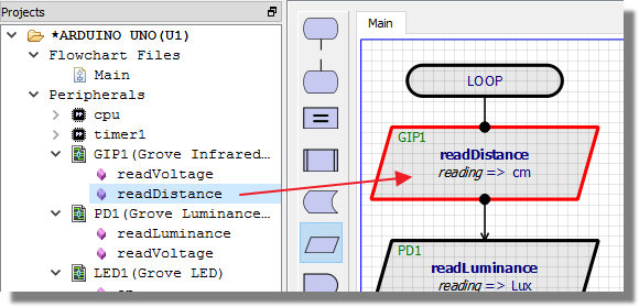
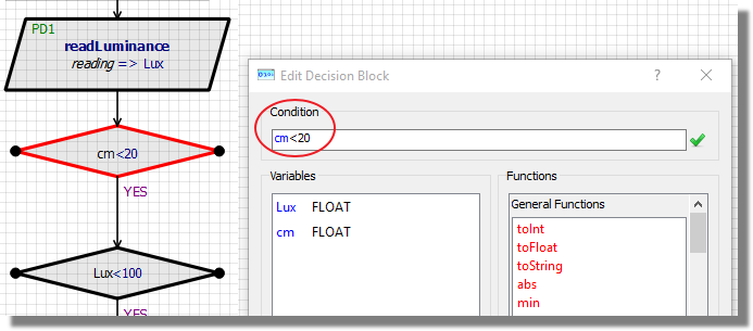
The proximity sensor can detect up to 80cm but we'll set our initial test to 20cm.
See Also:
http://wiki.seeedstudio.com/Grove-80cm_Infrared_Proximity_Sensor/
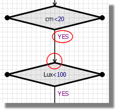
Since, we need both conditions to be true for the LED to turn on, make sure that the second decision is on the YES branch of the first decision.
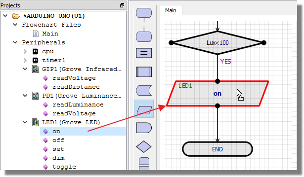
Next, drag and drop the led on method at the bottom of the YES branch.
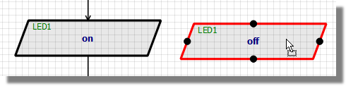
Finally, place the LED off method to the right of the main loop beside the LED on method.
Since we want the LED to turn off if either condition is false we can wire both NO branches from the decisions to this method.
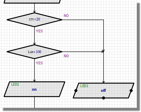
Finally, connect the bottom of the NO program branch back into the main program loop.
Simulating and Testing
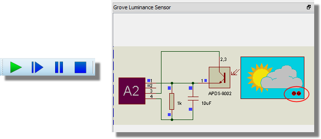
To test our program, all we need to do is press the play button and then adjust the distance display on the proximity sensor and the lux display on the luminance sensor.
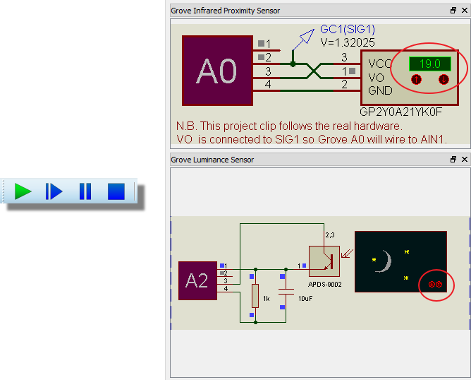
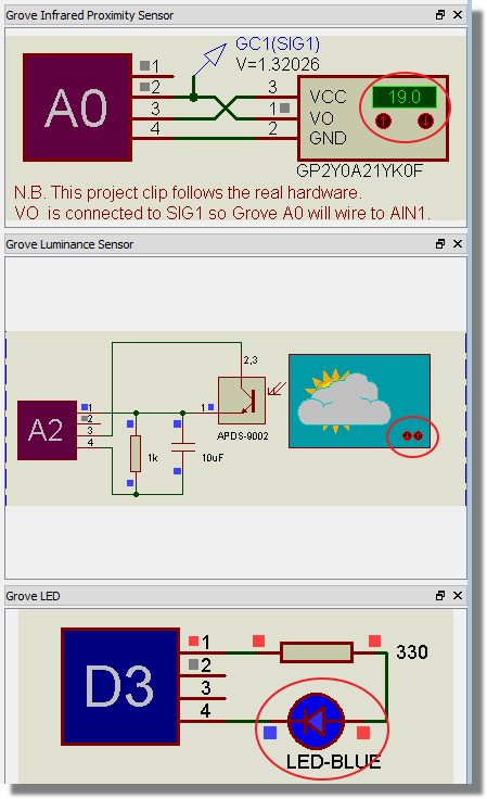
The LED should turn on when the distance value is less than 20 and it's a little cloudy.
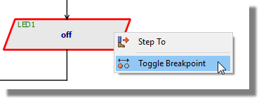
Pause the simulation and set a breakpoint on the LED off method.
Press play again to run the simulation and change either the distance or the light until the breakpoint triggers
You'll notice that both our variables are available in the variables display.
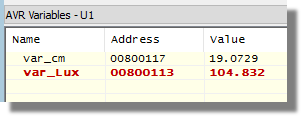
Comparing these values to the tested decisions will tell us which condition has failed.

As you single step via the icons at the top you'll notice the LED turn off.
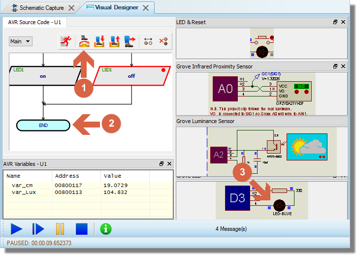
1, Single step once. 2, Notice the END block is highlighted. 3. LED has turned off
See Also:
Programming
Since everything seems to working in good order, the remaining task is to plug in the Arduino and program the real hardware. The process here is:
1) Plug the Grove sensors into the Grove baseboard in the same connectors as on the schematic. See also the golden rule discussed earlier.
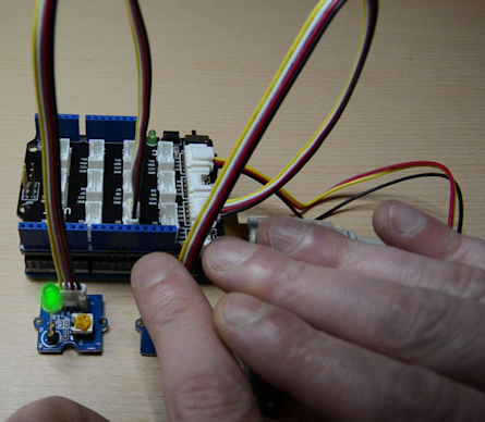
2) Connect the baseboard to the Arduino and connect the Arduino to the PC. Until you have something like so:
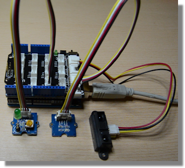
3) Click the program upload button in Visual Designer.

4) Test in hardware.
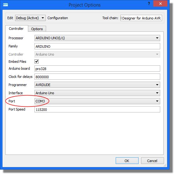
If the programming fails, click on the project settings icon (next to the icon shown above) to make sure the COM port and settings are correct.