TUTORIAL 4 : MOTOR CONTROL
Introduction
This tutorial shows how you can easily control both DC motors and Stepper motors with Visual Designer. We'll do this using the Arduino Motor Shield V1 R3.
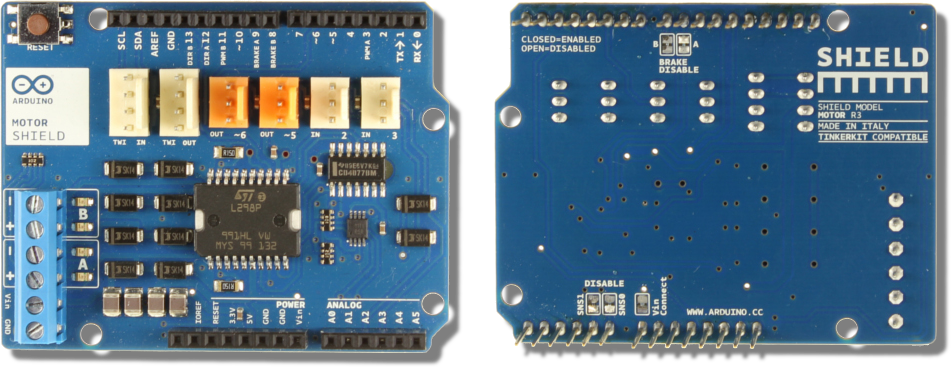
Front View Rear View
See Also:
https://www.arduino.cc/en/Main/ArduinoMotorShieldR3
You can experiment with Servo motors using the Grove Servo peripheral and you can also use BLDC motors by drawing on the schematic.
DC Motor Control
Start by creating a new Visual Designer Project and then Add the Arduino Shield with DC Motors in the normal way.
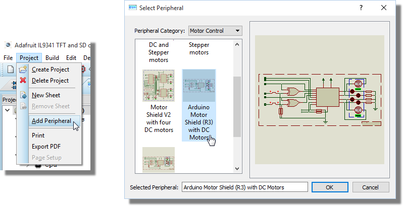
Note that under the Motor Control heading there are actually two shields. These are identical except that the first has the board configured and populated with two DC motors and the second is configured and populated with one stepper motor. In the real hardware of course you would need to configure and populate the shield manually according to which project you were programming the Arduino with.
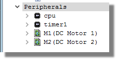
You should notice that in the Project Tree you now have two motors with associated methods.
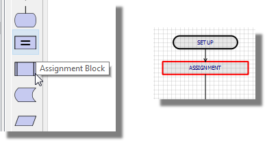
Let's write a small program to drive the motors in opposite directions. The first thing we want to do is initialise a variable for the speed of the motors so drag and drop an assignment block into the Setup routine (we only need to do this once).
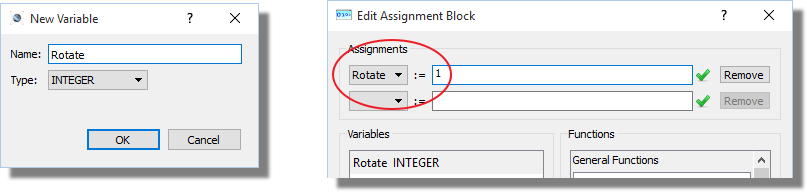
Edit the block, create a new variable and assign a value.
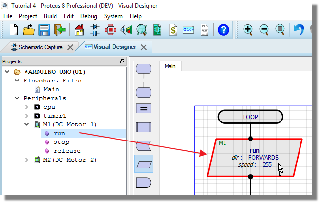
Now, let's drive the first motor forwards. Drag and drop the run methods into the loop routine.
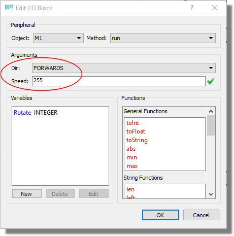
Edit the block, set the direction forwards and assign the speed to our variable.
Repeat the process for the second motor to send it spinning backwards.
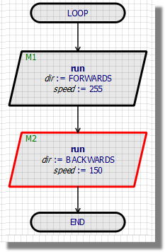
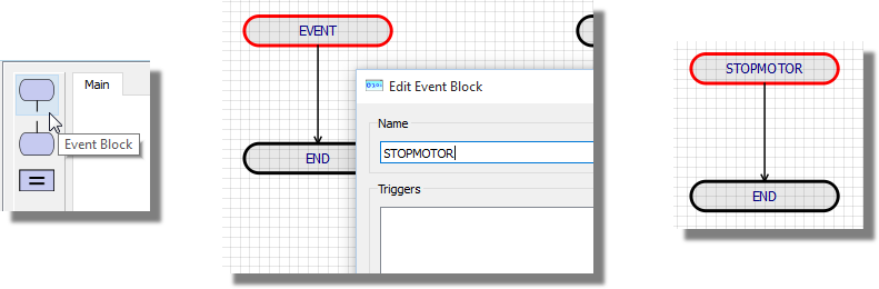
Next, we'll add a sub-routine to stop the motors. Drag and drop an Event block into an empty place, edit the Event block and give it a sensible name.
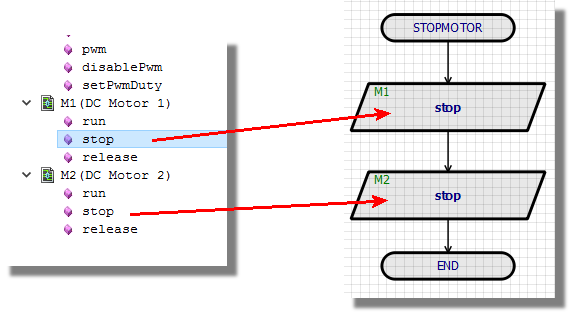
Now, drag and drop the stop routine for both motors into the sub-routine we've just added.
Finally, drag and drop a subroutine call block into the main loop and edit it to call our routine.
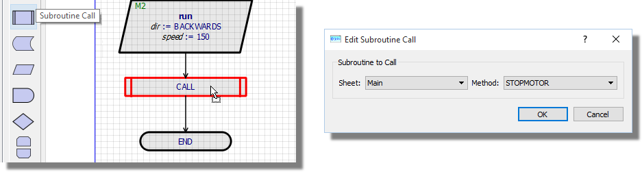
To see this in action press the pause button and then single step the code using the Step-Into icon at the top of the source window. You'll notice that the code executes through the sub-routine and then returns to the main loop.

We have most of the pieces of our program in place but we are starting and stopping the motors very quickly which isn't going to help them build momentum. Much better to add a delay in the drive phase and a similar time delay in the stop phase. Again, this is drag and drop from the flowblock menu onto the chart routines.
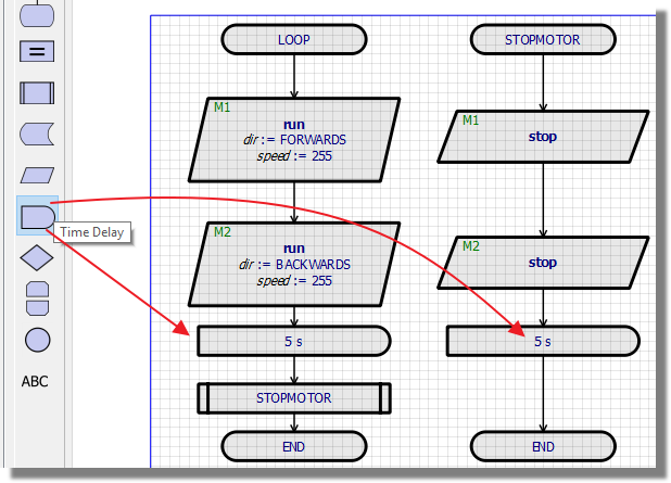
If you run the simulation now you can monitor the drive and spin down loops via the time display on the status bar

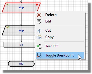
You could also pause the simulation, set a breakpoint and step the code. Unlike the real hardware the motors won't lose momentum when you are at a breakpoint - a real advantage to debugging in software.
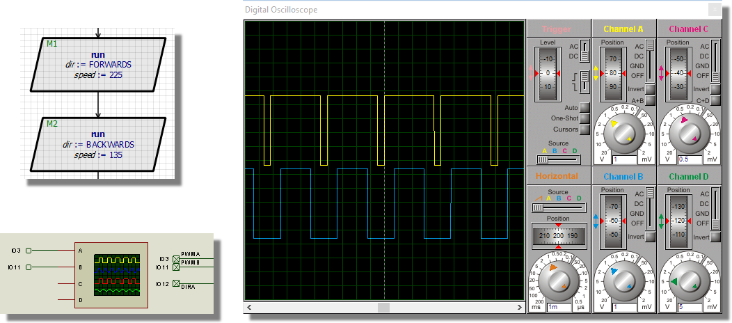
For more advanced analysis you could place and wire an oscilloscope on the schematic and watch the PWM waveforms drive the motor.
As always, you can program the physical board at any time via the upload button.

Stepper Motor Control
For the stepper motor we are using the same hardware shield (Arduino Motor Shield V1 R3) but configured for a single unipolar stepper motor. Start a new Visual Designer project and bring in the virtual shield via the Add Peripheral command.
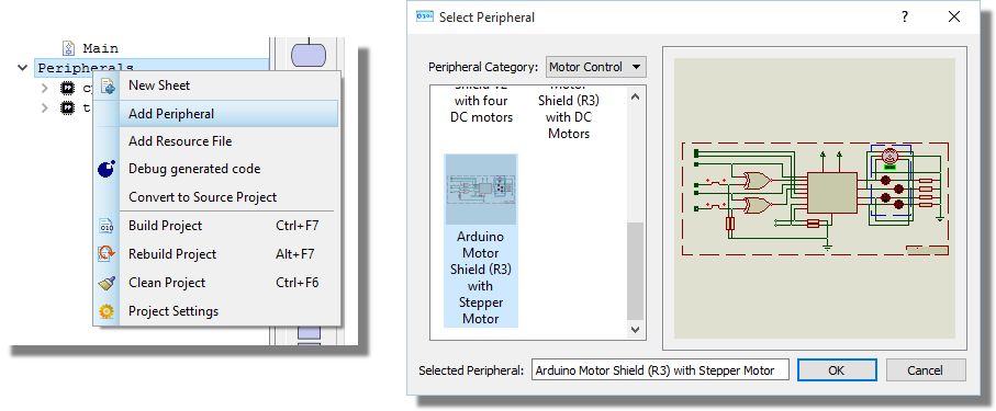
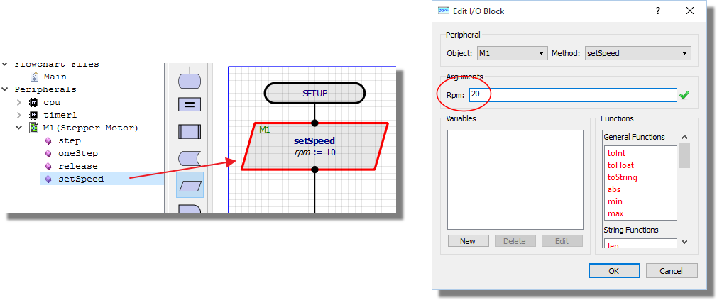
We'll design a small program to step the motor in one direction and then reverse direction and step backwards. Our first job is to define the speed which we can do by dragging the setSpeed() method into the Setup routine.
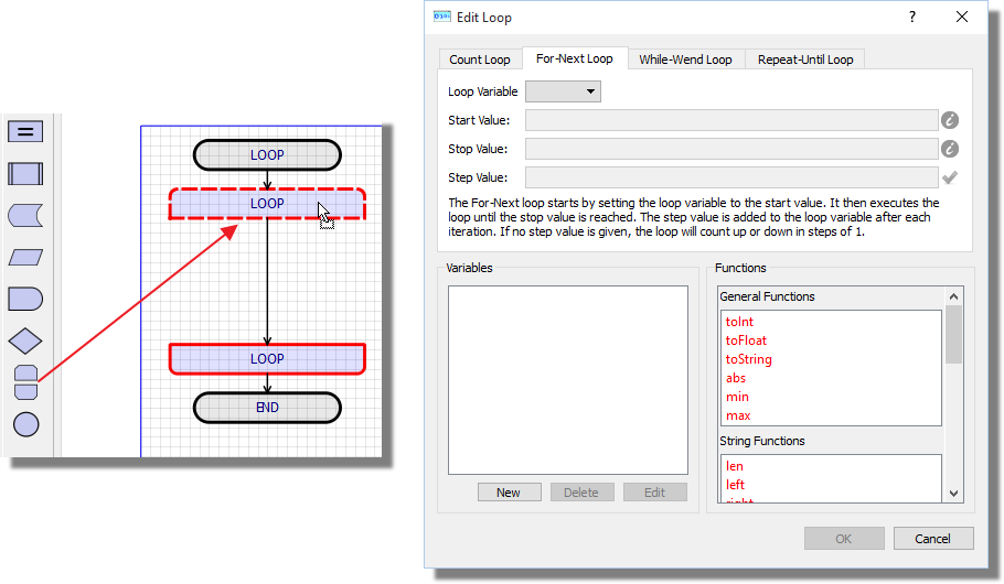
In order to step a set number of times we want to use a loop construct. Drag and drop one onto the Main (Loop) routine and edit the block.
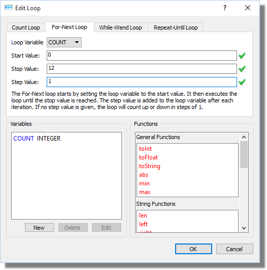
We'll use a For-Next loop here so add a variable for count, initialise to zero and let's go round the loop 12 times.
Now, drag the step() method of the motor inside our loop - you'll notice the colour change to indicate it's part of the loop construct.
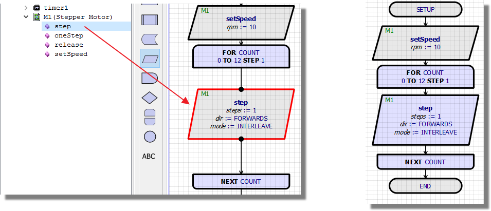
Edit the flowblock and make the number of steps 4 so that we get sensible movement, set the direction to forwards and the mode to interleave.
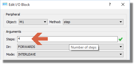
Single Mode means single-coil activation, Double mode means 2 coils are activated at once (for higher torque) and "interleave" mode means that it alternates between single and double to get twice the resolution (but of course its half the speed). Lots more info on this in various internet resources.
Add a modest delay after the step routine to allow the drive phase to complete before we iterate the loop.
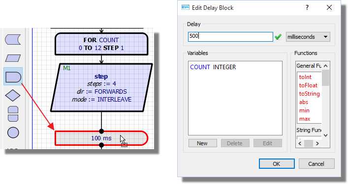
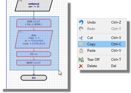
That's the forwards motion in place. Driving the motor in the opposite direction is identical except that we change the direction in the step routine. You can place a second loop and drag methods in or we can just use the trusty copy and paste. Drag a box with the right mouse around the loop and select copy from the resulting context menu.
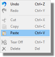
Next, right click (or CTRL+V) to paste a second set of blocks.
Drag them into place underneath the first loop, releasing the mouse when the top node appears with a dot.
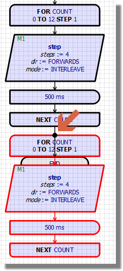
Finally, edit the step method and change the direction.
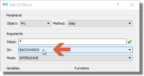
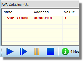
That's it. Press play and watch the motor step forwards and backwards or pause, set a breakpoint and single-step your program. Note that the counter variable is displayed in the variables window which will tell you instantly how many more iterations of your loop remain.