TUTORIAL 5: SCHEMATIC BREADBOARD
Introduction
So far in all of the tutorials we have used pre-existing Arduino shields or Grove modules for the hardware. There is however nothing to stop us designing our own hardware directly on the schematic . We will cover the basics in this tutorial with a button and an LED. Note however that there are literally thousands of parts that can be simulated in the Proteus libraries. Start by creating a new project with a schematic, no PCB and with Firmware for Arduino Uno using the Visual Designer Compiler for Arduino.
This tutorial is also covered by a short movie on the Labcenter Youtube channel.
Drawing on the Schematic
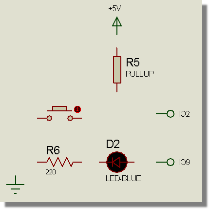
There is a good deal of documentation on schematic drawing in the main Proteus help files so we'll cover only in brief here. Our task is to draw the following circuitry on the schematic;
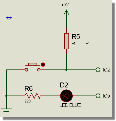
The three main steps are pick, place and wire.
Picking
To pick from the library select the 'P' button above the parts bin on the schematic. This presents us with the library browser. We are only interested in those parts that we can simulate so start by checking the box to filter the results.
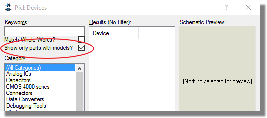
We will need an LED, a 220 Ohm resistor, a pullup resistor and a button, all of which we can find by typing keywords at the top left of the dialogue form.
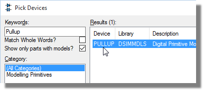
To pick a part into the parts bin, simply double click on the result.
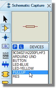
You may be asked if you want to replace the existing part. This will happen when you pick a part already in the parts bin; for example, there is already an LED in the parts bin because it's used in the Arduino Uno Shield.
See Also:
Schematic Tutorial : Basic Schematic Entry
Placing
To place a part, select it in the parts bin, left click once on the schematic, then drag into place and left click again to drop.
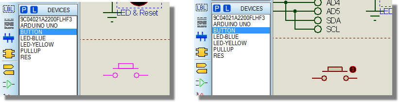
If you need to rotate, you can do this with the plus and minus keys on the keyboard during placement.
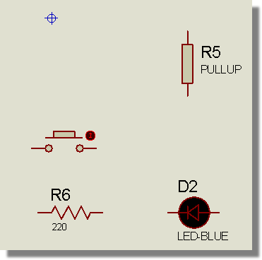
Place all of the parts approximately in position - something like the following:
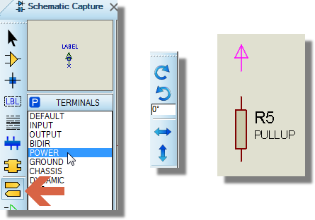
We can apply power and ground by selecting terminal mode and placing /rotating in the same way as we did the parts.
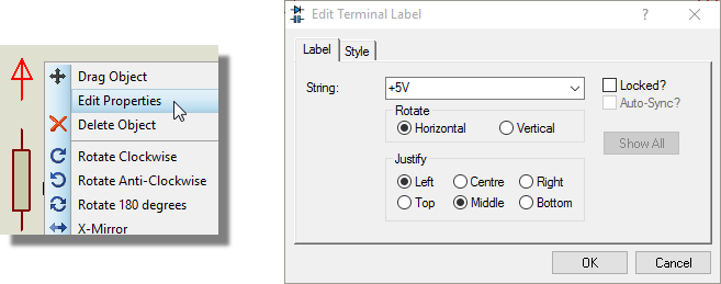
Edit the power terminal and specify the correct voltage.
We'll also need a terminal to connect our button and our LED up to the correct pin on the Arduino. We can use default terminals for this.
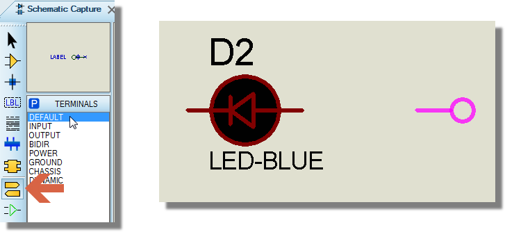
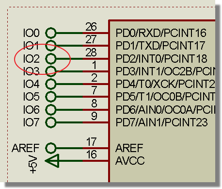
It is here that the hardware and the firmware designs start to merge. The best way to wait for a button press in firmware is via a pin change interrupt. This means however that we need to connect the button to a pin on the Arduino for which a pin change interrupt is available. On the Uno we can use IO2 for this and can connect the LED to any available IO pin.
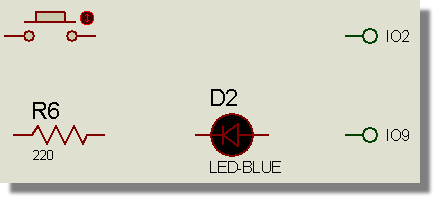
You want it to look like the one below (without the wires at this stage).
Wiring
Wiring on the schematic is point to point. First, hover the mouse over a pin until the cursor turns green and then left click
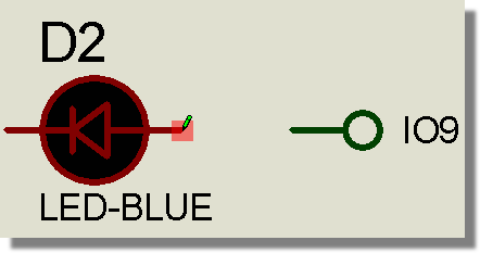
Next, move the mouse to the destination pin/wire until the cursor turns green again.
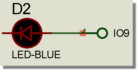
Left click the mouse again to complete the wire.
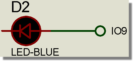
After wiring is complete your schematic should look like the following.
Remember the two terminals with the same name on the schematic have an 'invisible wire' between them so by wiring the button to a terminal called IO2 we have actually connected it to the IO2 pin on the Arduino chip.
See Also:
Schematic Reference Manual : Wiring Up
Designing our Program
Everything we have done so far is hardware design. The program design itself takes place on the Visual Designer tab. Unlike our other tutorials we don't have any external peripheral methods in the project tree so we will have to drive the electronics directly using the CPU methods.
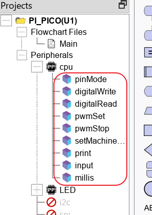
We'll start by dragging and dropping the pin change interrupt routine in to the Setup routine.
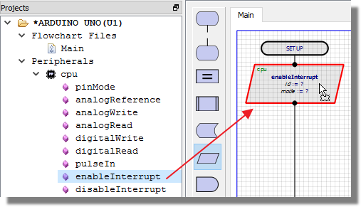
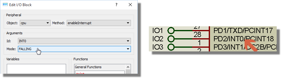
Now, there are two available interrupt pins on the Uno but we need to select INT0 because we wired the button onto IO2.

Similarly, we need to set the interrupt to trip on a falling edge because we wired the button to pull low when pressed.
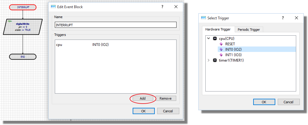
Now we need to handle the interrupt event. Drag and drop an event block onto the Flowchart Editor and edit. Give a sensible name and then specify the trigger as INT0.
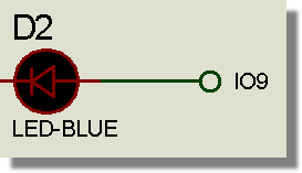
We are going to turn on an LED when the button was pressed so we need to write out a logic high on one of the IO lines. Specifically, it needs to be IO9 because that's where we wired the LED on the schematic.
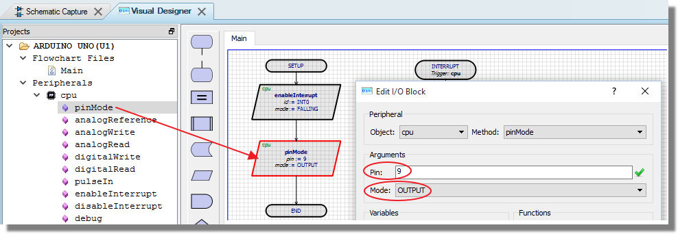
Start by setting the pin to be an output pin. We can do this directly in the Setup routine by dragging a pinMode routine on to the Flowline.
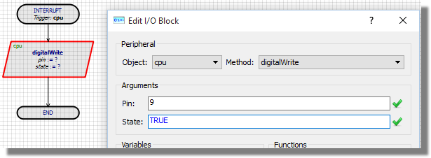
Then drag and drop the digitalWrite method into the interrupt handler, name the pin and set the state to true.
That's it. Press play to simulate, switch to the schematic tab and press the button to test.

To bring an area of the schematic into the Visual Designer we need to specify it as an Active Popup. To do this, stop the simulation, select Active Popup mode and drag a box with the left mouse around the components of interest.
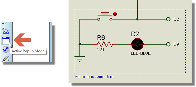
This time, when you press play you can test in Visual Designer via the Active Popups. It's a matter of preference in this case but, when debugging, it's often very useful to be able to see the circuit at the same time.
You can easily add a few blocks to change the program into a toggle or continue with developing the hardware on the schematic.
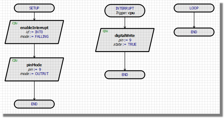
Your Flowchart project should finally look something like the following:
Interrupts are really useful but be aware that in the Arduino environment you are limited in what you can do. For example, attempting to write to an LCD inside an interrupt routine will simply fail because the Arduino stack for writing to the LCD itself uses interrupts. Caution is required.