Tutorial 1 : Flashing LED
Introduction
This tutorial covers the basics of project creation, working with flowcharts, raspberry Pi simulation and programming the real hardware. The actual goal of flashing the LED is kept as simple as possible so that we can cover the end-to-end process. Working with more complex peripherals and hats is covered in subsequent tutorials.
New Project Wizard
Visual Designer is integrated into the Proteus Design Suite and so we start our Visual Designer Projects from the Proteus Home Screen. The easiest and best way to create a Visual Designer Project is, unsurprisingly, through the New Flowchart Wizard.

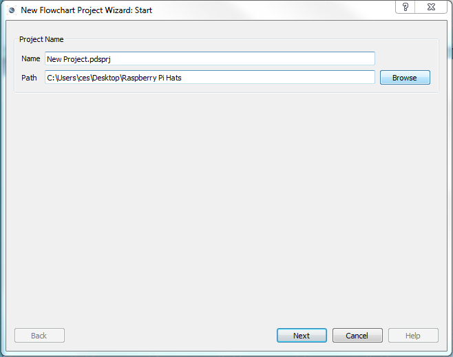
The first page allows you to select the name and destination of your project.
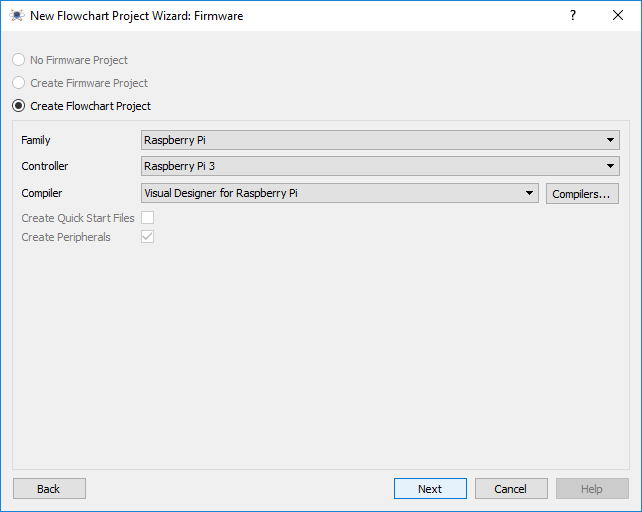
Next up is the firmware screen and it is here that we really define our Visual Designer project. First, we change the radio buttons at the top to the option for Flowchart Project and then we select the Raspberry Pi family and either the RPi3 or the RPi3 + GrovePi Hat from the controller combo box.
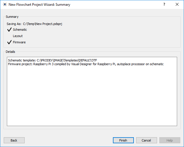
Finally, you will be presented with a summary page of your configuration.
After you exit the dialogue form the project will be created and you will see both a skeleton schematic with the Raspberry Pi processor placed and a skeleton chart project with the familiar Setup and Loop routines on the Editing Window.
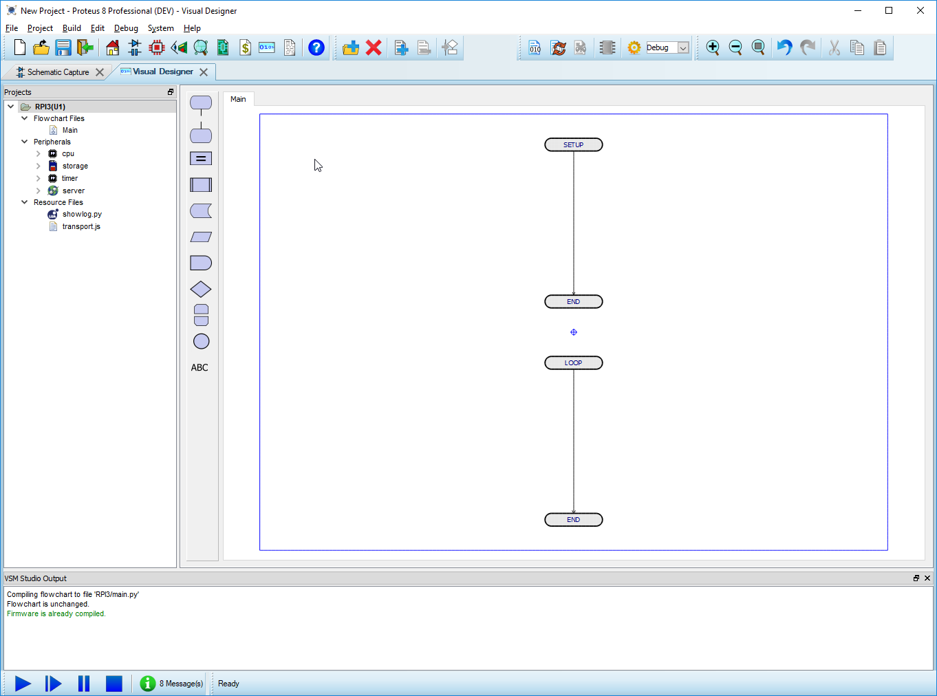
Now we are ready to start designing our project.
Adding a Peripheral
The first thing to do is to add the peripheral(s) for the project. These can be Raspberry Pi Hats or just little breakout peripherals. The Raspberry Pi does not need a Hat to operate and you can add peripherals which talk to the GPIO Pins Directly.
We'll be adding a Breakout LED. In Visual Designer, we right click on the Project Tree and select the Add Peripheral command. Next, switch to Breakout Peripherals and select one of the LED's.
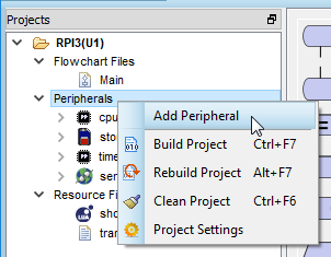
Add the Peripheral from the context menu command in VSM Studio
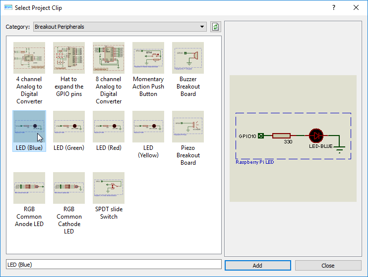
Double click on the LED to add it to the project.
Repeat the process to add a Breakout button. If you then switch to the schematic tab you will see that the 'virtual hardware' has been autoplaced for you.
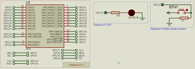
Schematic view with both LED and push button auto-placed.
To avoid clutter on the schematic, connections are made on the schematic by giving terminals the same name. Any terminals with the same name can be thought of having an invisible wire between them.
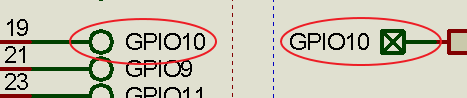
Terminals with the same name are considered connected together.
In real hardware, this equates to connecting the Breakout button and Breakout LED to the GPIO Pins on the Raspberry Pi
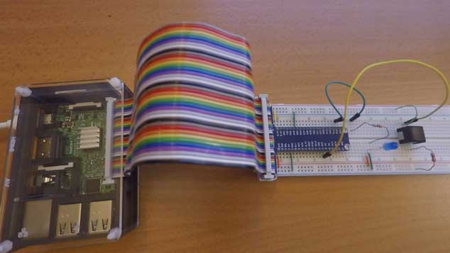
Note that you must attach the peripherals onto the same GPIO pins on the Raspberry Pi as they are designated on the Proteus schematic. You may need the pinout to see which GPIO pins go where.
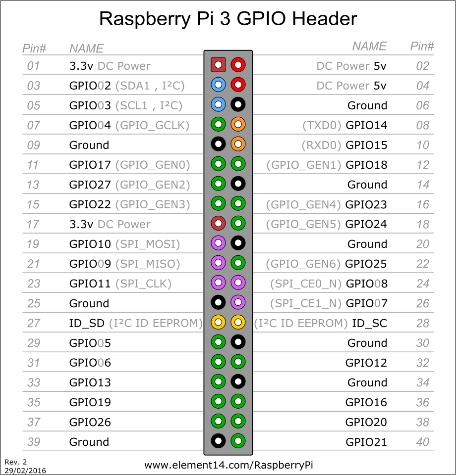
GPIO pins on the Raspberry Pi
You must also ensure that you don't have two peripherals with the same terminal label on the schematic; if you do, you need to switch to the schematic and edit the terminal labels on one of the peripherals. Some pins may need unlocking.
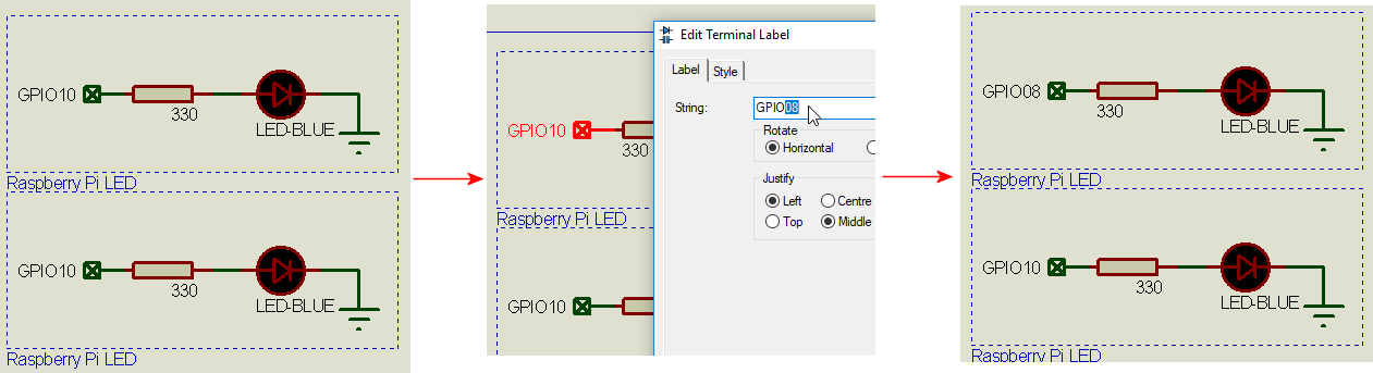
If you have two terminals with the same name they will be connected ! Need to edit one and re-assign to another GPIO line.
Flowchart Design
Back in Visual Designer, you'll notice that the Project Tree now has two entries under the peripherals section.
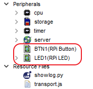
The beauty of Visual Designer is that you can expand the peripherals to find a list of methods. These methods are the primary way in which we interact with the hardware. For example, drag and drop the 'On' method of the LED into the loop routine
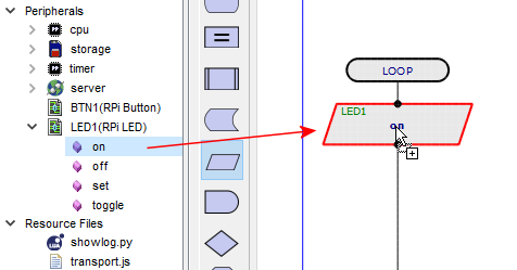
Drag and Drop methods onto the program.
To test this simply press the play button. The program will compile, the simulator will start and the LED will turn on. You can see this either via the Active popup at the right of Visual Designer or by switching to the schematic tab.
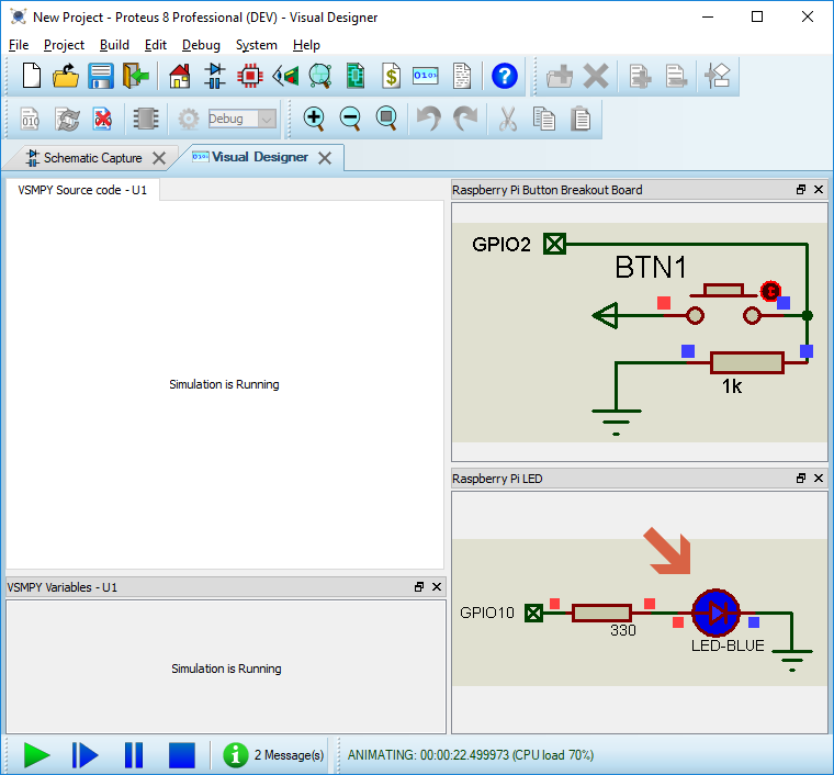
Run the simulation to test results.
Press stop to exit the simulation and we'll extend our program to switch the LED on and off with a button press. You'll notice that the button has no methods in the project tree
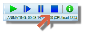
Stop the simulation when finished.
The only sensible information we need from the button is to know whether it has been pressed and for that we have what we call a 'sensor function'. A sensor function returns either TRUE or FALSE depending on whether the basic peripheral function is true or not. For example, the sensor function for a button will return TRUE when the button is pressed and FALSE if it isn't. Similarly, the sensor function for an LED will return TRUE when the LED is on and FALSE when the LED is off. Place the sensor function for the button by dragging and dropping from the button itself onto the loop function of the flowchart
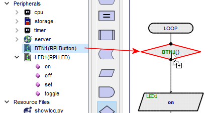
Drag the sensor function onto the flowchart
You will notice that it appears as a decision block. Sensor functions always return TRUE or FALSE and a decision block allows us to split our code into two conditional paths. Your loop routine should currently look something like the following.
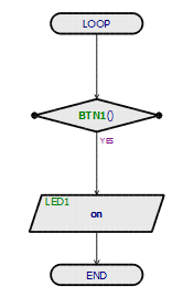
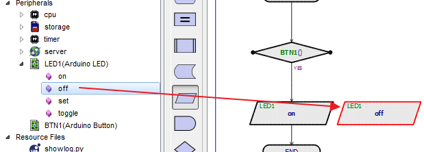
We are constantly testing the button to see if it is pressed and we are turning on the LED if it is. However, we still need to tell the program what to do if the button is not pressed. We want the LED to turn off so lets drag and drop that method into space alongside the ON operation.
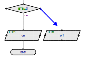
Now, we need to wire from the decision block to the top of the OFF command. To place a flowline click on an output node (the decision block), move the mouse to an available input node (top of the OFF routine) and click the mouse again.
Similarly we need to connect the flow from the bottom of the OFF command back into the main loop.
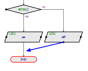
Your program should now look like the following.
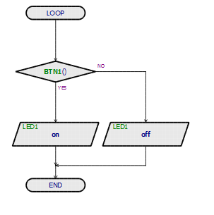
Having made this change, our program now turns the LED off when the button is down and on when the button is released. To compile and test, first press the play button and then use the mouse to press the button down..
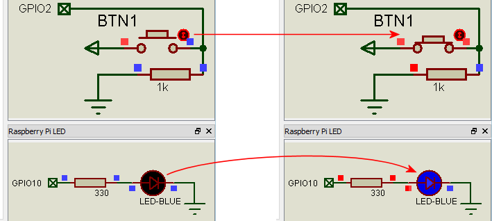
Programming the Hardware
This section assumes that you have completed the initial configuration of the Raspberry Pi.
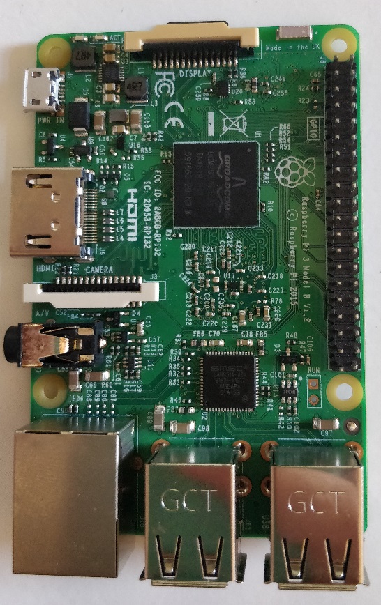
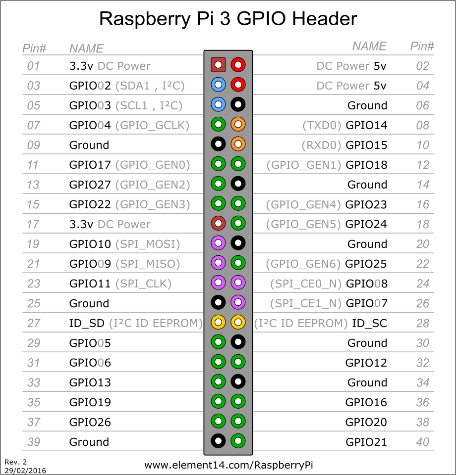
Here on the Left is a Raspberry Pi 3, and on the Right is the pinout for the GPIO Pins. The very first thing you need to understand is the orientation. Both these images are oriented in the same way. The top 2 pins are both power (Left pin is 3.3V and Right pin is 5V). You can find this pinout on the raspberry pi website. Some of the Raspberry Pi I cases have the pinout engraved into it making it very easy to find each pin. Failing that, you can use a template or make one with a little bit of card to make life easier.
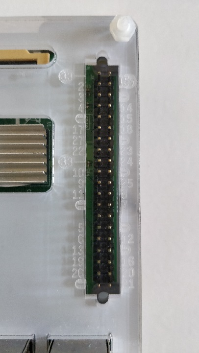
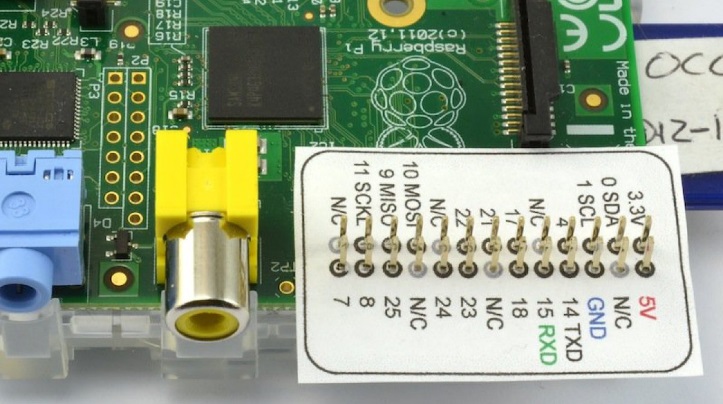
Engraved casing or simple template to identify lines on the header block.
Now in our program we connected the LED to GPIO 10. Not to be confused with Pin 10 which is GPIO 15. GPIO and Pin numbers are very different so make sure you connect the correct one. Just like the schematic we've included a protection resistor to prevent he LED from getting damaged by the current from the Raspberry Pi.
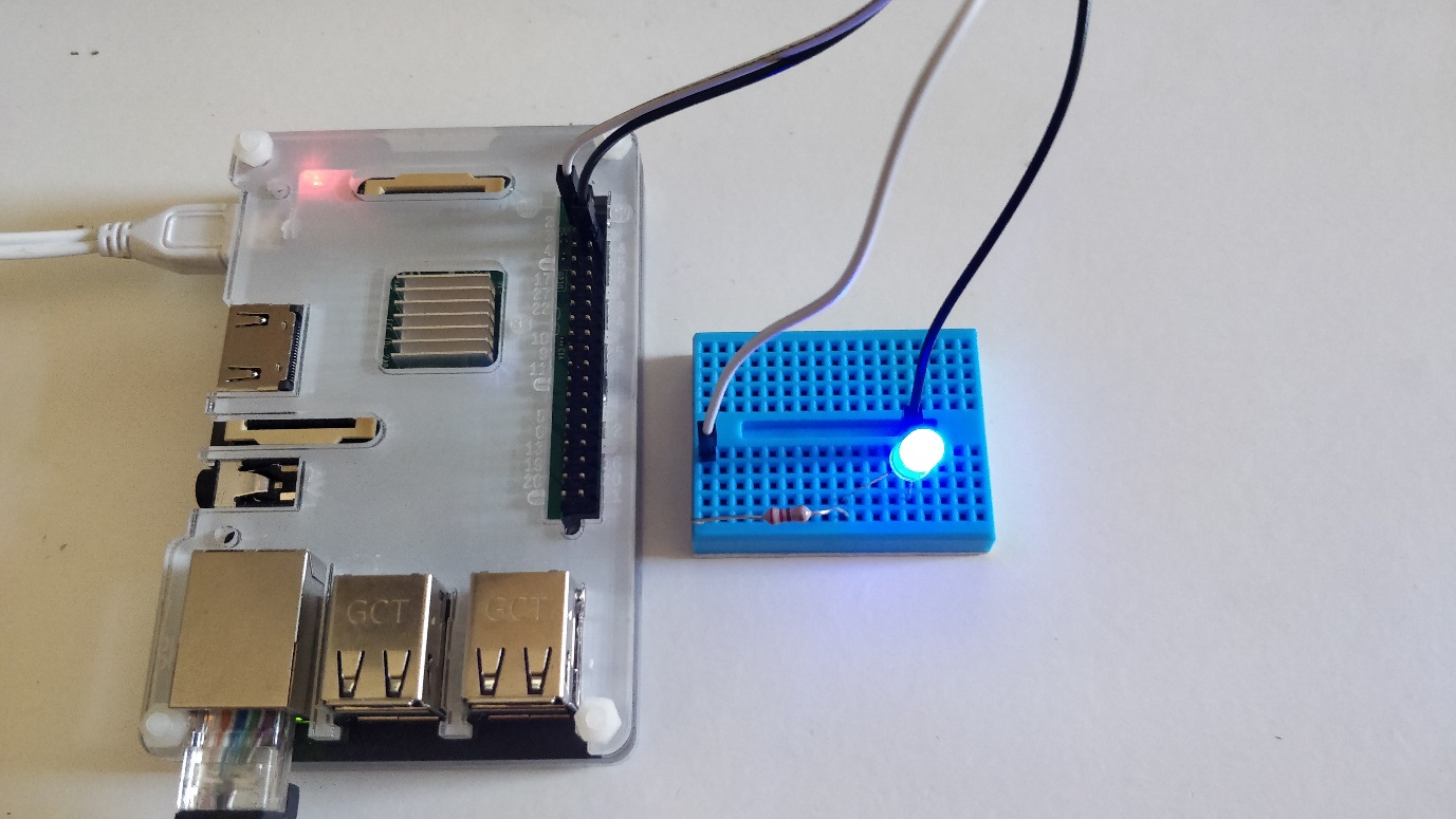
Here you can see we've used Male to Female wires connecting the Raspberry Pi to the Breadboard.
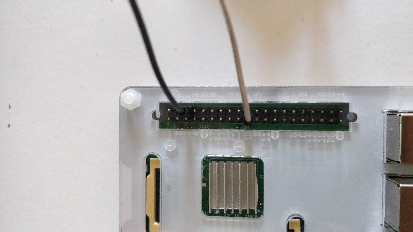
Assuming all is correct your led should flash just like the project.