WRITING GEOMETRIC MODELS IN ARES
Overview
Geometric Models are ideally suited for use in the 3D Viewer as they consume no disk space, are contained in the Proteus PDSPRJ file and are quick to render. This is especially true for large pin count SMD devices where a STEP file can come in at 10Mb or more. It is therefore well worth learning a little about how to create and define scripted models - at the very least it will help you achieve model completion in the rare instances where you cannot source STEP models for a part.
The idea is simply that we type in parameters according to the type of package in order that our 3D footprint more accurately reflects a real world device. Clearly the type of model depends entirely on the dimensions of a physical part so we’ve summarized the information below.
Writing a Geometric Model
1) Select Package mode, pick the package you want from the libraries and place on an empty area of the editing window.
2) Tag the part and invoke Make Package from the Library Menu.
3) From the 3D mechanical model tab, select geometric model option.
4) Use the Labcenter scripting language to define the shape and type of the model. This is covered in the language reference guide below
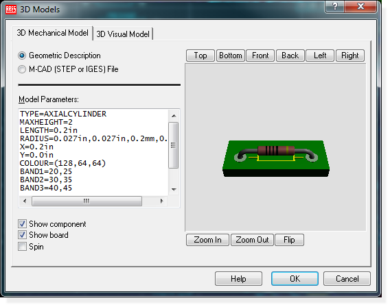
Note that a Geometric model must always start with TYPE=X where 'X' is one of the following:
- CUBOID
- EXTRUDED (extrudes from the silk screen). N.B the package must have a closed silkscreen path.
- NONE
Language Reference Guide
Body Type EXTRUDED (Default)
This method, used in the default case where no TYPE property has been specified, attempts to form a closed polygon from a graphic on a particular layer, and then extrudes that polygon in the Z dimension. Should there be no closed polygon type extruded behaves in the same way as TYPE=NONE (detailed below), although additional processing is done to determine this case.
The LAYER property can be used to override which board layer is used to form the basis of the closed polygon, where the following values are available:
SILK MECH1 MECH2 MECH3
MECH4 KEEPOUT OCCUPANCY
The default for the layer property the silk screen layer.
The following standard properties are also available:
| Property | Description |
COLOUR |
R,G,B value for the colour of the body. |
MINHEIGHT |
Specifies the height of the bottom of the body from the top of the board. |
MAXHEIGHT |
Specifies the height of the top of the body from the top of the board. |
X |
Specifies the X-axis distance of the origin of the body to the origin of the board graphic. |
Y |
Specifies the Y-axis distance of the origin of the body to the origin of the board graphic. |
ANGLE |
The angle of the body relative to the packages angle (e.g. ANGLE=45). |
Assignment of properties in the script block is made in the normal way:
<property>=<value>
with the exception of the colour property which is assigned as:
COLOUR=(R,G,B)
Body Type NONE
Setting this body type removes both the body and the pins, leaving a simple hole in the board.
TYPE=NONE
However if you require a JUMPER for example then you can add the parameter PINTYPE=STRAIGHT which will redraw the pins. For more information, please see the subsequent section on Pin Types.
Body Type CUBOID
The following details the provided properties for a cuboid body type:
| Property | Description |
TYPE |
Sets the body type (CUBOID in this case). |
COLOUR |
R,G,B value for the colour of the body. |
MINHEIGHT |
Specifies the height of the bottom of the body from the top of the board. |
MAXHEIGHT |
Specifies the height of the top of the body from the top of the board. |
X |
Specifies the X-axis distance of the origin of the body to the origin of the board graphic. |
Y |
Specifies the Y-axis distance of the origin of the body to the origin of the board graphic. |
SX |
Specifies the size of the width of the cube. |
SY |
Specifies the size of the length of the cube. |
ANGLE |
The angle of the body relative to the packages angle (e.g. ANGLE=45). |
Examples of this type include the SMT resistors and the QFN footprints in our libraries. If you select and place one of these parts and then invoke the '3D Models' command from the context menu (as above) you should see that the following properties have been added:
TYPE=CUBOID
COLOUR=(75,75,75)
X=0.250mm
Y=-0.250mm
MINHEIGHT=0.100mm
MAXHEIGHT=0.800mm
SX=7.000mm
SY=7.000mm
PINTYPE=CUBOID
PINMAX=0.1mm
This duly produces a 3D cuboid as shown in the preview window. Adjusting values will live update the preview window, allowing you to quickly customize to your requirements.
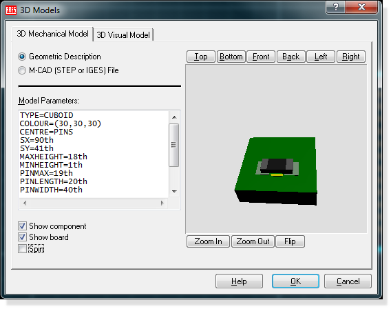
0805 resistor with the specified parameters applied
Body Type AXIALCYLINDER
The following details the provided properties for a axial-cylinder body type:
| Property | Description |
TYPE |
Sets the body type (AXIALCYLINDER in this case). |
COLOUR |
R,G,B value for the colour of the body. |
MAXHEIGHT |
Specifies the height of the top of the body from the top of the board. |
X |
Specifies the X-axis distance of the origin of the body to the origin of the board graphic. |
Y |
Specifies the Y-axis distance of the origin of the body to the origin of the board graphic. |
LENGTH |
Sets the length of the cylinder. |
ANGLE |
The angle of the body relative to the packages angle (e.g. ANGLE=45). |
RADIUS |
Controls the radius of the cylinder about the cylinders axis. |
BEND |
Sets the position and colour of the resistance bands. |
The final two parameters are worthy of further discussion as they allow provide considerable depth of control and also enable automatic colour coding of resistor bands for example.
The RADIUS Property
The RADIUS property is of the form:
RADIUS=P1,P2,P3,P4
Where:
- P1 Controls the vertical radius of the cylinder.
- P2 Controls the horizontal radius of the cylinder.
- P3 Controls the depth of the radius towards the cylinders axis.
- P4 Controls the depth of the radius along the cylinders axis
Essentially, the first two parameters allow for the production of elliptical bodies and the second two parameters extend the functionality to allow for the creation of torpedo shapes.
Note that it is not necessary to supply all four parameters if the desired shape does not require them. The default for the first radius parameter is a small nominal value such that the cylinder is visible. The default for the second radius parameter is to take the value of the first radius parameter. The default for the third radius parameter is zero. The default for the fourth radius parameter is to take the same value as the third
The BAND Property
The BAND property is of the form:
BANDx=P1,P2,(r,g,b)
Where x can be a number from 1 to 9 (up to 9 bands permissible) and:
- P1 The starting point of the band along the axist of the cylinder (as a percentage of the cylinder size.
- P2 The end point of the band along the axis of the cylinder (as a percentage of the cylinder size)
- RGB The colour value of the band. If omitted, the default colour will be calculated from the components value field, allowing for automatic colour coding of resistors etc.
The vast majority of resistors in our libraries are created in this way. If, for example, you pick a RES40 from the libraries and invoke the 3D Visualisation command from the right click context menu you should see that the following properties have been added:
TYPE=AXIALCYLINDER
MAXHEIGHT=2
LENGTH=0.2in
RADIUS=0.027in,0.027in,0.2mm,0.2mm
X=0.2in
Y=0.0in
COLOUR=(128,64,64)
BAND1=20,25
BAND2=30,35
BAND3=40,45
BAND4=50,55
BAND5=80,85,(128,128,0)
In particular, note that no colour parameter has been specified for the majority of the bands as we want the 3D viewer to calculate the colour codes for us depending on the value of the resistor. What we are saying is that BAND1 starts 20% along the cylinder and stops 25% of the way along, BAND2 starts 30% of the way along and stops at 35% of the way along, etc. etc.
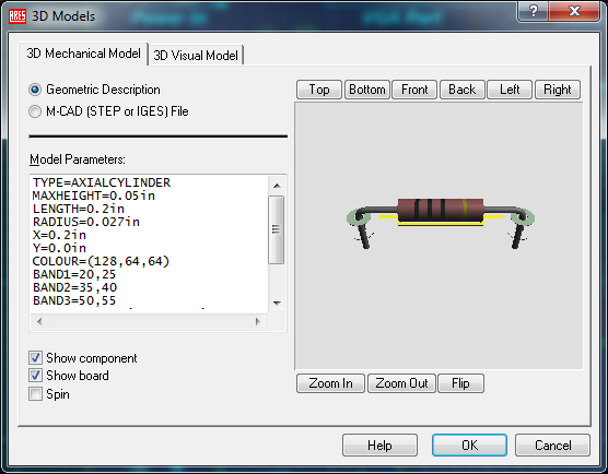
RES40 parameters as specified above
The calculation of the colour band values only takes place when the 3D Viewer is invoked on a board. Feel free to try this, first editing the RES40 and setting a value and then invoking the 3D Viewer from the Output Menu.
Pin Types
Having customized the body type it is sometimes also necessary to change the pin type for the 3D model.
There are six styles of pins available for use as follows:
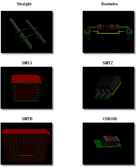
If you do not require a pin at all then set the type to be PINTYPE=NONE
The default pin type in a given situation is dependant on the pad style in ARES and also on whether the pad is below the footprints 3D body.
For through hole pads, the default pin style is BENTWIRE unless the pin is under the package body or there is no package to attach to, in which case the default becomes STRAIGHT. For surface mount pads, the pin style is SMTZ unless the pad is below the package body or there is no package to attach to, in which case the default becomes SMTJ.
These defaults tend to work well but if need be you can assign a specific pin type in the normal way. i.e. PINTYPE=xxxxxx. Additional properties that can be applied to pins are detailed below:
| Property | Description |
PINCOLOUR |
R,G,B value for the colour of the pin. |
PINMAX |
This indicates the highest extent of the pin from the surface of the board and is used by all pin types. |
PINMIN |
This indicates the lower extent of the pin from the surface of the board. For through pins this will likely be a negative value, for surface mount it is likely to be zero. |
PINDIAMETER |
For STRAIGHT and BENTWIRE pins, this controls the diameter of the pin. For SMTB it controls the diameter of the hemisphere. |
PINLENGTH |
For SMTJ and SMTZ this controls the length of the base of the pin. |
PINTHICKNESS |
For SMTJ and SMTZ this controls the thickness of the pin. |
PINWIDTH |
For SMTJ and SMTZ this controls how width of the pin. |
PINMOVE |
This moves the pins closer or further away from the boundary of the package body by the fixed amount specified. |
Two additional properties, called PINANGLEABS and PINANGLEREL are available if needed. They allow you to more accurately position one or more of the pins. The following are some examples of usage:
PINANGLEABS=90 : all pins are rotated 90 deg absolute.
PINANGLEABS[1]=90 : Pin 1 is rotated 90 deg absolute.
PINANGLEREL=90:
All pins are rotated 90 deg relative to the angle formed by the
pin centre to the nearest point on
the extruded body.
PINANGLEREL[1]=90
: Pin 1 is rotated 90 deg relative to the angle formed by the pin centre
to the nearest point on
the extruded body.
PINANGLEREL or PINANGLEABS will not be required for the majority of cases and is only used to fix pins in rare cases. It os not recommended that you use this as a standard parameter.