CAN MODELS
Introduction
The CAN models are a family of behavioural automotive nodes that populate a Controller Area Network bus with realistic vehicle traffic. Each model is a single schematic component that connects to the bus through two pins, CANH and CANL, and presents a popup window in which gauges sweep, lamps illuminate and sliders inject stimulus while the simulation runs. They model the behaviour of a real ECU on the wire, the messages it sends, the messages it acts on, and how it reacts to faults, without modelling the silicon inside it.
Because the nodes are behavioural rather than full microcontroller models, a complete vehicle network of a dozen ECUs simulates at the cost of a single processor and advances responsively. This makes them ideal as the traffic environment around a student's own MCU: the student writes firmware for one node and runs it against a busy, realistic bus made up of these models. The traffic they produce is decoded by name on the CAN Bus Analyser when a matching .dbc database is loaded.
Every model is a self-contained vehicle part. The popup is the interaction surface, the schematic pins carry only the CAN bus, so a node can be dropped onto the bus and driven entirely from its window with no additional wiring.
CAN Protocol Primer
A CAN bus is a single pair of wires shared by every node, with no master in charge. Any node may start transmitting when the bus is idle, and every node hears every message. A CAN message does not carry a destination address; it carries an identifier that names the message itself, and it is broadcast to the whole bus. Each node decides for itself which identifiers are of interest and ignores the rest. This is the central idea to hold on to: a brake pedal does not send a signal to a lamp, it broadcasts a “brake” message that any interested node may act on.
Because all nodes share one wire, two that begin transmitting at the same moment are separated by their identifiers: the lower-numbered identifier wins, and the other node stops and tries again later, with no message lost or corrupted. The identifier therefore also sets the message priority. A frame carries the identifier, a data length and up to eight data bytes (in classical CAN), protected by a checksum, and every receiver of a good frame acknowledges it on the bus.
The data bytes only mean something once you know their layout: which bits make up which signal, and how to turn a raw count into a real value such as km/h or degrees. That description lives in a DBC database file. CAN also looks after its own integrity: each node keeps error counters, and a node whose transmit errors climb too high takes itself off the bus (a state called bus-off) so that one faulty node cannot jam the network. Identifiers, broadcast delivery, priority by arbitration, signals defined by a database, and error states are the ideas the rest of this topic relies on.
How It Works in Proteus
In Proteus the CAN bus is drawn on the schematic as the two signals CANH and CANL, shared by every node. Each behavioural model is a single component that joins that bus through those two pins and plays the part of one real ECU on the vehicle. Your own microcontroller joins the same bus and runs your firmware alongside the models, so it sees exactly the traffic they produce.
Between any microcontroller and the wire sit one or two pieces of “real” silicon, modelled accurately rather than behaviourally. Knowing their separate jobs makes the wiring obvious:
- The transceiver (for example the MCP2551, TJA1050 or SN65HVD23x family) is the physical layer. It converts the single transmit and receive lines of a CAN controller into the differential CANH / CANL pair the bus actually carries, and back again. It knows nothing of frames or identifiers; it just drives and senses the two wires. Every node needs one to reach the bus.
- The controller is the protocol engine that builds and receives frames and performs arbitration, filtering and error counting. A pyboard or STM32 has a CAN controller built in, so it needs only a transceiver. An MCU with no on-chip CAN uses a standalone controller instead, the MCP2515 (or the MCP2518FD for CAN FD), which connects to the MCU over SPI and then reaches the bus through a transceiver in turn.
- Neither part has a bus address. As the primer explained, CAN addresses messages, not devices: a frame carries a message identifier and there is no node address. A transceiver is invisible to the protocol, and a controller is known only by the identifiers of the messages it sends and the acceptance filters that decide which identifiers it receives.
When the simulation runs, every model transmits its own messages onto the shared bus at the right times and listens for the messages it cares about, just as a real ECU would. A frame that one node transmits is delivered to all the other nodes; a receiving model acts on it (a lamp lights, a gauge moves, a tell-tale comes on) and may broadcast messages of its own in response. The bus therefore carries a continuous, realistic flow of traffic that you can watch, stimulate and join with your own node. Because each model reproduces only the behaviour seen on the wire and not the processor inside the ECU, a whole network of these nodes costs about as much to simulate as a single microcontroller, and the bus keeps advancing responsively while you work.
The identifiers and byte layouts that each model uses are built into the model itself: a given part always transmits and listens on the same set of messages. They are not a component property and you do not assign them; the Bus Message Map below simply documents the messages the models use. The DBC file you load on the analyser is a separate, matching description of that same fixed protocol. It controls how the traffic is labelled and decoded for you, not what the models actually put on the wire, so loading, changing or leaving out the database changes only what you see, never the behaviour of the bus.
In short, the protocol is fixed by the models and the DBC simply gives it names. Load the matching database on the analyser (its DATABASE property) to read the traffic by name; the models behave identically with or without it.
Common Conventions
The models share a common set of properties, accessible from the Edit Component dialogue (right-click the part, then left-click to edit). The most widely used are listed below; properties specific to one model are described in its own section.
| Property | Description |
|
SHOW_POPUP |
Shows (1) or hides (0) the model's popup window. Default 1. |
|
FAULT_MODULE |
Injects a node-level fault for fault-handling exercises. Values include DEAD, MUTE and BUSOFF (the node stops transmitting or acknowledging), and message-level faults such as STUCK, GARBLE, WRONGID, DROPOUT, OFFRATE and FLOOD. Several may be combined as a comma list, and a fault may be scoped to one message with an @<id> suffix. Blank for normal operation. See Fault Injection and Diagnostics. |
|
FAULT_BANNER |
When 1 (default) a red banner is drawn across the popup whenever a fault is active, so the faulted node is obvious at a glance. |
|
DIAG_ECU_INDEX |
The OBD-II / UDS responder index used when a node answers a scan tool. Each diagnostic-capable model has a distinct default so several can coexist on one bus. |
|
SHOW_BASIC / SHOW_ADVANCED |
On the tiered nodes (for example ABS / ESP), select how much of the popup is shown: a simplified Basic panel or the full Advanced panel. The equivalent <NODE>_LEVEL property sets the same tier by number. These affect only the display; the bus traffic is unchanged. |
|
<NODE>_RATE_MS |
The transmit period of the node's main message in milliseconds. Each node has a realistic default (for example 20 ms for the fast chassis sensors, 100 ms for slower status frames). A floor prevents an unrealistically fast rate from flooding the bus. |
The bus traffic produced by these models is summarised in the message map below. Load the matching .dbc (for example vehicle.dbc, powertrain.dbc or lighting.dbc) on the analyser to see these messages decoded by name.
Bus Message Map
The principal messages exchanged by the models are listed below, in order of identifier and therefore of arbitration priority.
| ID | Message | Source and purpose |
|
0x0C0 |
SAS_DATA | Steering Sensor: steering angle and rate, with a rolling counter and checksum. |
|
0x0D0 |
SRS_STATUS | SRS / Airbag: belt reminders, crash and deployment stage, with a rolling counter and checksum. |
|
0x100 |
ENGINE_DATA | Engine ECU: RPM, throttle, load, temperatures. |
|
0x101 |
ENGINE_DATA2 | Engine ECU: extended sensor suite (airflow, manifold pressure, lambda, timing, knock). |
|
0x110 |
VEHICLE_DYNAMICS | Vehicle Dynamics: road speed and per-wheel speeds. |
|
0x130 |
ENGINE_DTC_STATUS | Engine ECU: MIL lamp, stored DTC count. |
|
0x141 |
ENGINE_SECURE | Engine ECU: authenticated engine data (optional). See CAN Security. |
|
0x150 |
FUEL_DATA | Engine ECU: fuel consumed and instantaneous consumption. |
|
0x152 |
FUEL_SYSTEM | Fuel System: fuel level, low-fuel warning, pump state, range. |
|
0x160 |
ABS_ESP_STATUS | ABS / ESP: stability activity, yaw rate, lateral acceleration, with a rolling counter and checksum. |
|
0x161 |
ABS_WHEEL_BRAKE | ABS / ESP: per-wheel brake pressures. |
|
0x163 |
TCM_STATUS | Transmission Control Module: selected gear, shift state, output torque, temperature. |
|
0x164 |
EPS_STATUS | Electric Power Steering: assist level, column torque, mode, with a rolling counter and checksum. |
|
0x180 |
IMMO_STATUS | Immobiliser / PEPS: key and authentication state; hosts UDS SecurityAccess. |
|
0x190 |
SUSP_STATUS | Adaptive Suspension: ride heights, target height, damping mode. |
|
0x1A0 |
EPB_STATUS | Electronic Parking Brake: brake state, source, motor current. |
|
0x200 |
BCM_LIGHTING | Lighting Console: the lighting command (brake, indicators, headlamps…). |
|
0x208 |
DOOR_COMMAND | Student or body controller: lock and window-target requests. |
|
0x210 |
BCM_DOORS | Body Control Module: door, boot, lock and window state. |
|
0x220 |
TRAILER_STATUS | Trailer Module: hitch presence and trailer lamp / bulb status. |
|
0x230 |
REAR_LIGHT_STATUS | Rear Lighting Cluster: bulb-fault status. |
|
0x240 |
TPMS_STATUS | TPMS ECU: per-wheel pressures and low-pressure warnings. |
|
0x250 |
IDS_ALERT | Intrusion Detection: security alert broadcast. See CAN Security. |
|
0x300 |
MUX_ID | Diagnostic Multiplex: a single multiplexed teaching message. |
|
0x7DF / 0x7E8… |
OBD-II / UDS | Scan Tool requests and per-ECU diagnostic responses (ISO-TP). |
The identifiers are not arbitrary. As the primer noted, the numerically lowest identifier wins arbitration, so the lowest IDs are the highest-priority messages. The map follows the convention used in real vehicle networks: the most time-critical chassis-safety and powertrain messages (steering, airbag, engine, vehicle dynamics) occupy the low 0x0C0 to 0x1A0 range, body and comfort functions (lighting, doors, trailer, tyres) sit in the 0x200 block, and diagnostics use the high 0x7xx range, where their lower priority cannot delay control traffic. Identifiers are also grouped by function, with gaps left between the groups so that a further node has a natural home at the right priority.
This particular assignment is chosen by Labcenter for the Proteus models; a real manufacturer's CAN matrix is proprietary and differs in its exact identifiers and signal layouts. It is representative, though, in the ways that matter for learning: priority is encoded in the identifier, the time-critical traffic is given the low identifiers, identifiers are allocated in functional blocks, and diagnostics live in the standard OBD-II range. A student who understands this map will recognise the same principles in any production vehicle network.
Engine ECU
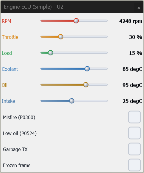
The Engine ECU popup with its live sliders, profile selector and fault toggles.
Device: ENGINE_ECU
Models the engine controller as a source of powertrain data and as an OBD-II / UDS diagnostic responder. It is the busiest single node on the network and the natural anchor of most powertrain exercises.
It streams ENGINE_DATA (0x100: RPM, throttle, load, coolant, oil and intake temperatures), an extended sensor suite on ENGINE_DATA2 (0x101: airflow, manifold pressure, boost, lambda, ignition timing, knock count), fuel figures on FUEL_DATA (0x150: consumed and instantaneous consumption) and a diagnostic summary on 0x130, and it answers scan-tool requests over ISO-TP. A PROFILE property animates the engine (Idle, Cruise, Sweep), and touching a slider returns it to Manual. Popup fault toggles raise readable trouble codes: Misfire (P0300), Low Oil (P0524), garbage transmission and frozen frames.
Fuel level is not part of FUEL_DATA. It is owned by the Fuel System node on 0x152, so that one node is the single source of the fuel gauge.
The Engine ECU can also act as the genuine authenticated sender for the security unit. Set its SECOC property to 1 and it additionally emits ENGINE_SECURE (0x141), described under CAN Security.
Example
Select the Cruise profile to oscillate RPM and load smoothly, then toggle Misfire: a scan tool on the bus reads the stored P0300 code and the dashboard lights its check-engine tell-tale.
Vehicle Dynamics
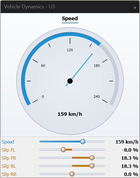
The Vehicle Dynamics popup with the road-speed slider, per-wheel slip controls and profile selector.
Device: VEHICLE_DYNAMICS
Models the chassis as the source of road speed and the four individual wheel speeds, the signals that the ABS, ESP and instrument nodes depend on.
It transmits VEHICLE_DYNAMICS (0x110: road speed and four wheel speeds). The popup carries a road-speed slider and a per-wheel slip control for each wheel. A PROFILE property can drive the speed automatically (Urban, Highway, Sweep) or follow a scripted drive cycle: set PROFILE to Script and give DRIVE_CYCLE a timeline of time and speed points, which the node replays as a looped, piecewise-linear speed curve. Dragging the speed slider drops it back to Manual.
Steering angle and selected gear are not produced here. Steering comes from the Steering Sensor on 0x0C0 and the gear from the Transmission Control Module on 0x163, so that each is single-sourced.
Example
Set PROFILE to Sweep and the road speed ramps up and down automatically, sweeping the dashboard speedometer; add wheel slip to the rear wheels to model a loss of traction that the ABS / ESP node then reacts to.
Fuel System
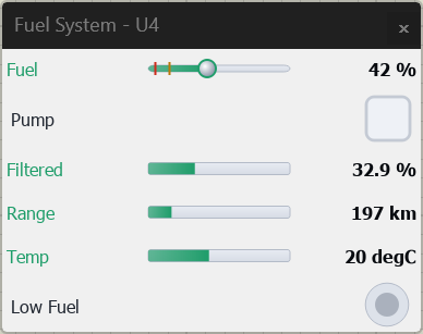
The Fuel System popup with the fuel-level slider, pump control and the range and low-fuel readouts.
Device: FUEL_SYSTEM (aliases FUEL)
Models the fuel-tank sender and pump, and is the single source of the fuel gauge on the bus.
It transmits FUEL_SYSTEM (0x152: fuel level, an anti-slosh filtered level, a low-fuel warning, pump status, estimated range and fuel temperature). The low-fuel warning is hysteretic, so it latches on below a low level and clears only once the level rises comfortably above it, and the range is derived from the filtered level. The popup has a fuel-level slider, a pump toggle and readouts for the filtered level, range and temperature.
Example
Drag the level down through the low-fuel threshold: the warning lamp latches on, the range readout falls, and the dashboard low-fuel tell-tale comes on. A sensor fault raises the fuel-level circuit code (P0463) for a scan tool to read.
Transmission Control Module
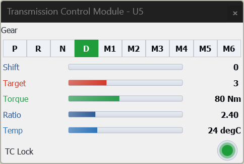
The Transmission Control Module popup with the PRND and manual-gate gear selector and the torque, ratio and temperature gauges.
Device: TCM (aliases TRANSMISSION)
Models the automatic transmission controller and is the single source of the selected gear on the bus.
It transmits TCM_STATUS (0x163: gear, shift state, torque-converter lock, target gear, output torque, gear ratio and transmission temperature) and consumes ENGINE_DATA (0x100) so that its illustrative output-torque and shift model follows engine speed. The popup is a PRND and manual-gate selector with gauges for shift state, torque, ratio and temperature.
Example
Select D and raise the road speed on the Vehicle Dynamics node: the transmission shifts up through its gears, the ratio steps down and the instrument cluster shows the gear change.
Steering Angle Sensor
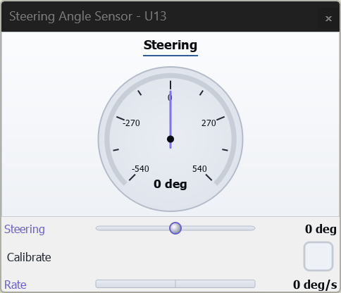
The Steering Angle Sensor popup with its signed steering dial, centre-origin steering slider and calibrate control.
Device: STEERING_SENSOR (aliases SAS)
Models the steering angle sensor, a fast, safety-relevant chassis sensor, and is the single source of steering angle on the bus.
It transmits SAS_DATA (0x0C0) at a high rate, carrying steering angle, steering rate and a calibrated flag. The frame also carries a rolling counter and a checksum, the kind of end-to-end protection real safety messages use, which the ABS / ESP node validates on receipt. The popup shows a signed steering dial and a centre-origin slider to steer, plus a calibrate control; an uncalibrated or faulted sensor raises the steering-sensor code (C0051).
The rolling counter and checksum make this node ideal for teaching message integrity. Corrupt it with FAULT_MODULE=GARBLE and watch the ABS / ESP node reject the implausible data and enter a safe state.
Example
Steer hard over with the slider while the vehicle is moving, then garble the frame: the ABS / ESP node detects the broken checksum, latches its plausibility fault and disables stability control.
ABS / ESP
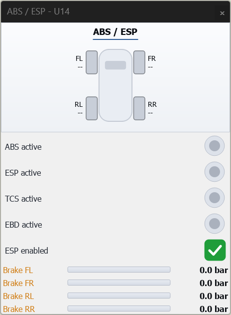
The ABS / ESP popup showing the per-wheel brake-pressure map and the stability status lamps.
Device: ABS_ESP (aliases ABS, ESP)
Models the anti-lock braking and electronic stability controller. It is a consumer as much as a source: it reads the wheel speeds and steering angle from other nodes and computes its response.
It consumes VEHICLE_DYNAMICS (0x110) and SAS_DATA (0x0C0, whose counter and checksum it validates), and transmits ABS_ESP_STATUS (0x160: ABS, ESP, TCS and EBD activity, yaw rate, lateral acceleration, with its own counter and checksum) and ABS_WHEEL_BRAKE (0x161: per-wheel brake pressures). The illustrative control logic decides when to intervene from wheel slip and a steering-versus-yaw plausibility check; it teaches the data flow of stability control rather than real vehicle dynamics. The node is tiered: SHOW_BASIC shows a simplified panel and SHOW_ADVANCED the full brake-pressure map and status lamps. A module fault raises C0040, and a persistent steering-implausibility raises C0045.
Example
Apply slip to one wheel from the Vehicle Dynamics popup and the matching corner of the brake-pressure map responds as ABS modulates it; introduce a steering-versus-yaw contradiction and the ESP fault latches.
Electric Power Steering
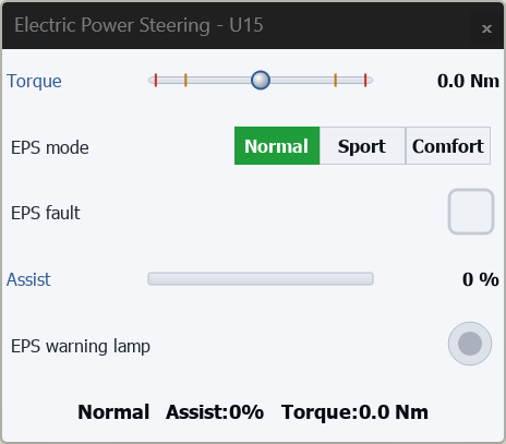
The Electric Power Steering popup with the column-torque slider, mode selector and assist gauge.
Device: EPS (aliases ELECTRIC_POWER_STEERING)
Models the electric power steering controller and its speed-sensitive assist.
It transmits EPS_STATUS (0x164: assist level, column torque, steering mode, fault and warning flags, with a rolling counter and checksum) and optionally reads road speed and steering angle to shape its assist map, so assist falls off as speed rises. The popup has a centre-zero column-torque slider, a Normal / Sport / Comfort mode selector, an assist gauge and a fault control. A fault raises the EPS code (C1511).
Example
Raise the road speed and apply column torque: the assist gauge shows less assist at speed than at parking pace. Switch to Sport for a firmer map.
Electronic Parking Brake
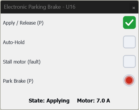
The Electronic Parking Brake popup with the apply and release controls and the motor-current readout.
Device: EPB (aliases PARKING_BRAKE)
Models the electronic parking brake as an actuator with a state machine.
It transmits EPB_STATUS (0x1A0: brake state, the source of the request, hill-hold and auto-hold flags, the park-brake warning lamp and the motor current). Applying or releasing runs the motor for a travel time while the current ramps to a peak, and a stall guard trips a fault if the motor runs too long. The popup has apply, release and auto-hold controls, a motor-stall fault control, the warning lamp and a live motor-current readout. A fault raises the EPB code (C100D).
Example
Press Apply and watch the state pass from Releasing through Applying to Applied as the motor current peaks and falls; enable the stall fault and the actuator trips into its fault state.
Adaptive Suspension
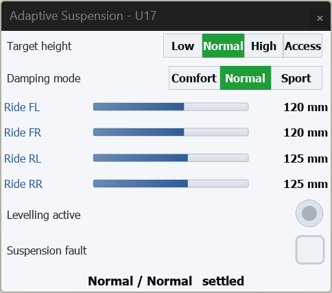
The Adaptive Suspension popup with the target-height and damping selectors and the four ride-height gauges.
Device: ADAPTIVE_SUSPENSION (aliases SUSPENSION)
Models an adaptive air-suspension controller.
It transmits SUSP_STATUS (0x190: the four ride heights, the target height, the damping mode and a levelling-active flag). Each corner ramps smoothly toward the selected target, and a fault freezes the heights. The popup has a target-height selector (Low, Normal, High, Access), a damping selector (Comfort, Normal, Sport), four ride-height gauges and a fault control. A fault raises the suspension code (C1A01).
Example
Select Access height and watch all four corners drop together as the levelling-active flag comes on, then select High and they rise.
SRS / Airbag
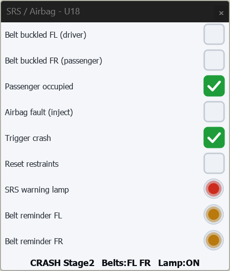
The SRS / Airbag popup with the belt and occupant controls, the crash trigger and the warning lamps.
Device: SRS_AIRBAG (aliases SRS)
Models the supplemental restraint (airbag) controller.
It transmits SRS_STATUS (0x0D0: a system-OK flag, a latched crash-detected flag, belt reminders, occupant detection and a deployment stage, with a rolling counter and checksum). The popup has belt-buckled and occupant controls, a crash trigger that latches and steps the deployment stage, and a reset control, alongside the SRS warning and belt-reminder lamps. An airbag fault raises the airbag code (B0001).
Example
Leave the driver belt unbuckled and the belt-reminder lamp comes on; press the crash trigger and the deployment stage advances while the crash flag latches until reset.
Immobiliser / PEPS
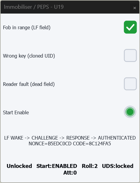
The Immobiliser popup showing the passive-entry authentication sequence and the start-enable lamp.
Device: IMMOBILISER (aliases PEPS, IMMO)
Models the immobiliser and passive-entry, passive-start system, and is the access-control node of the network.
It transmits IMMO_STATUS (0x180: key-present, authenticated, start-enable and security-unlocked flags, the immobiliser state and a rolling counter). It performs two independent authentications. The first is a passive-entry sequence: a key-fob wake, a challenge, and a rolling-code response validated against the stored key, with a cloned-key control to demonstrate rejection. The second is the standard UDS SecurityAccess seed-and-key exchange used by a scan tool. Both are described, with worked figures, under CAN Security. A reader fault raises the immobiliser code (B1681).
Example
Place the fob in range and the authentication sequence completes and start-enable comes on; select the cloned-key control and the same sequence is rejected and start-enable stays off.
Lighting Console
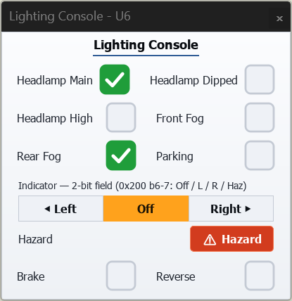
The Lighting Console popup: the switch panel and the Off / Left / Right / Hazard indicator selector.
Device: LIGHT_CONSOLE (legacy alias BCM)
Models the driver's lighting switch console, the source of the lighting command on the bus. It is a transmit-only node that turns switch inputs into a broadcast message.
The popup is a panel of switches (headlamp main, dipped and high, front and rear fog, parking, brake, reverse) plus an Off / Left / Right / Hazard indicator selector. Toggling any switch is packed into BCM_LIGHTING (0x200) and broadcast periodically (CYCLE_MS, default 50 ms); the indicator state blinks at BLINK_FREQ_HZ.
Only one node may transmit 0x200 at a time. If a student MCU is to take over the lighting command, disable or remove the console first, or the two transmitters will contend and the lamps will flicker.
Example
Click Brake on the console and both brake lamps light on the rear cluster; select Left and the left indicators blink in step on every cluster on the bus.
Front Lighting Cluster
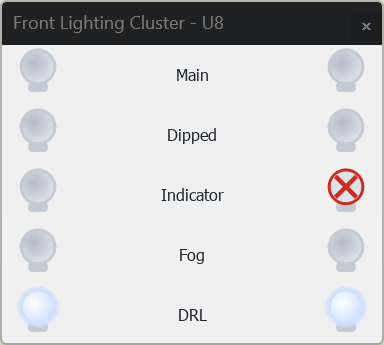
The Front Lighting Cluster popup with the main, dipped, indicator, fog and daytime-running lamp pairs.
Device: FRONT_LIGHTING
Models the front lamp cluster: main beam, dipped beam, indicator and fog lamps, plus automatic daytime running lights.
It receives BCM_LIGHTING (0x200) and drives the headlamp, indicator and fog pairs accordingly, illuminating the daytime running lights automatically whenever the headlamps are off. The popup shows each lamp pair and lets you break a bulb by clicking it. Dipped-beam brightness is adjustable through DIP_BRIGHTNESS.
Example
Run with no headlamp command and the daytime running lights sit at a dim glow; send a 0x200 frame selecting dipped beam and the main lamps take over.
Rear Lighting Cluster
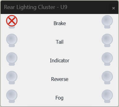
The Rear Lighting Cluster popup with its five lamp pairs, one shown with a broken bulb.
Device: REAR_LIGHTING
Models the rear lamp cluster: brake, tail, indicator, reverse and fog lamps, each as a left and right pair with realistic PWM-dimmed brightness.
It receives the lighting command BCM_LIGHTING (0x200) and lights the matching lamps; the popup shows each lamp pair live. Clicking a lamp toggles its bulb health (a broken bulb is shown with a red cross), and the cluster broadcasts its bulb-fault status as REAR_LIGHT_STATUS (0x230) and reports the matching diagnostic trouble codes to a scan tool. A command watchdog (CMD_TIMEOUT_MS) darkens the lamps if the command stops arriving.
Example
Wire the cluster to the bus, run, and send a 0x200 frame with the brake bit set (from the console or the analyser's Send tab): both brake lamps light in the popup. Click one to break the bulb and watch the fault appear on 0x230.
Body Control Module
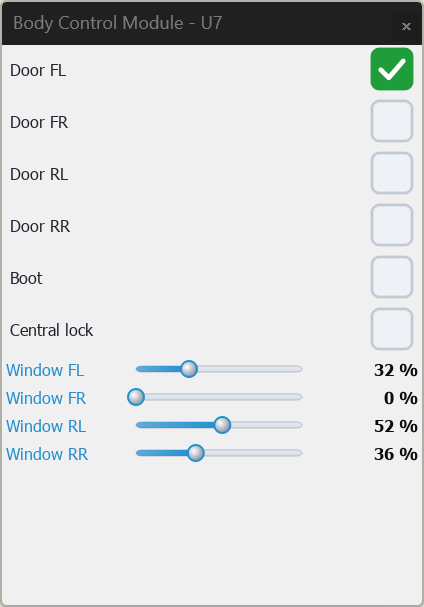
The Body Control Module popup with the door and lock switches and the four window sliders.
Device: BODY_BCM
Models the body controller responsible for doors, windows and central locking, distinct from the lighting console.
It broadcasts door, boot, lock and window state as BCM_DOORS (0x210) and accepts lock and window-target requests as DOOR_COMMAND (0x208). The popup has switches for each door, the boot and central locking, and sliders for the four windows, which glide smoothly toward their target.
Example
Drag a window slider to 50% and watch it glide open over about a second while the percentage updates live on 0x210; a student MCU can command the same window by sending 0x208.
TPMS ECU
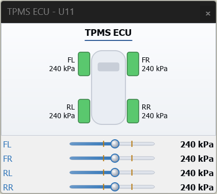
The TPMS popup with the four-corner tyre view and a per-wheel pressure slider.
Device: TPMS
Models a tyre-pressure monitoring ECU, broadcasting per-wheel pressures, low-pressure warnings and sensor-alive flags. The signal layout is illustrative; real TPMS protocols are manufacturer-proprietary.
It transmits TPMS_STATUS (0x240) and answers diagnostic requests. The popup shows a four-corner tyre view with a pressure slider per wheel and fault buttons for a slow leak, a blowout and a dead sensor; dropping a wheel below the warning threshold turns that corner amber and sets the warning flag.
Example
Drag the rear-left pressure below the warning threshold (or press its Leak button): the corner turns amber, 0x240 reports the warning, and a scan tool reads the low-pressure trouble code.
Instrument Panel
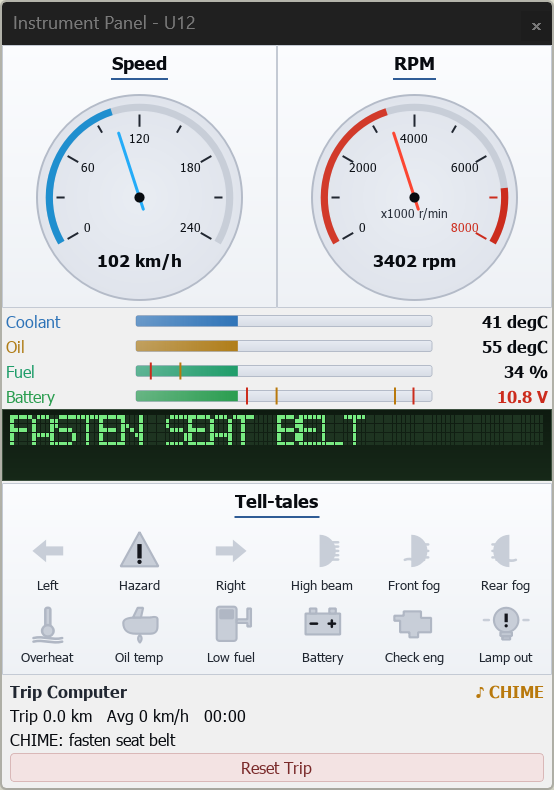
The Instrument Panel in its Dashboard layout, with both dials, the gauges, tell-tales and LCD strip.
Device: INSTRUMENT_PANEL (legacy aliases INSTRUMENT_CLUSTER, DASHBOARD, SPEEDOMETER)
Models the driver's instrument display: speed and RPM dials, coolant, oil, fuel and battery gauges, warning tell-tales and an LCD message strip. It is receive-only, driven entirely by signals from the rest of the bus.
A single LAYOUT property selects the composition: 0 Speedometer (one dial), 1 Cluster (both dials, two gauges, tell-tales) or 2 Dashboard (all gauges, full tell-tales and LCD). It reads speed from 0x110, engine data from 0x100, gear from 0x163, fuel from 0x152, indicators and lamp faults from 0x200 / 0x230, doors from 0x210, tyres from 0x240 and the MIL from 0x130, lighting the matching gauge or tell-tale as each arrives.
It also acts as the peer that surfaces a silent node. A dead or muted source cannot report its own failure, so the cluster watches the messages it expects and, if one stops arriving within LOSTCOMM_MS (default 1500 ms; set 0 to disable), raises a lost-communication trouble code for that source that a scan tool can read.
Example
Set LAYOUT=2 for a full dashboard, then run an Engine ECU and Vehicle Dynamics node alongside it: the tacho and speedo track their broadcasts live, and breaking a rear bulb lights the lamp-out tell-tale. Mute the Engine ECU and, after the timeout, the cluster raises a lost-communication code for it.
Trailer Module
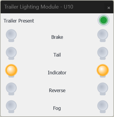
The Trailer Module popup with its lamp panel and the hitch control.
Device: TRAILER
Models a towed lamp set that mirrors the vehicle's rear lamps, gated on hitch presence, and reports its own bulb status back to the vehicle.
It receives the lighting command BCM_LIGHTING (0x200) and drives its brake, tail, indicator, reverse and fog lamps when hitched, and reports presence and bulb faults as TRAILER_STATUS (0x220). Connecting the hitch runs an automatic lamp test; presence is set by the PRESENT property, a HITCH input pin or a popup button.
Example
Hitch the trailer and its lamps sweep through a self-test, then follow the car's indicators and brake; unhitch it and the lamps go dark while 0x220 reports it absent.
ISO 7638 Coupler
Device: ISO7638_COUPLER
Models the ISO 7638 trailer connector that carries the CAN pair across the hitch between vehicle and trailer. It has no popup.
It is a gated, transparent bridge: while COUPLED is 1 it joins the trailer side to the vehicle bus and drives its DETECT output high; set COUPLED to 0 and the trailer is electrically isolated from the bus.
Example
Place the coupler between a vehicle bus and a Trailer Module, then toggle COUPLED to model plugging and unplugging the trailer mid-simulation.
Trailer Lamps
Device: TRAILER_LAMPS
Models a “dumb” analogue trailer lamp board with no CAN interface, with lamps lit directly from their analogue feed wires.
It has no bus connection; instead it reads the PWM lamp-feed inputs driven by the car-side trailer wiring, low-pass filters them, and shows the resulting steady brightness in its popup. Use it where the teaching point is the physical lamp feed rather than the CAN message.
Example
Drive its lamp-feed pins from a controller's PWM outputs and the popup shows each lamp's brightness without flicker.
Scan Tool
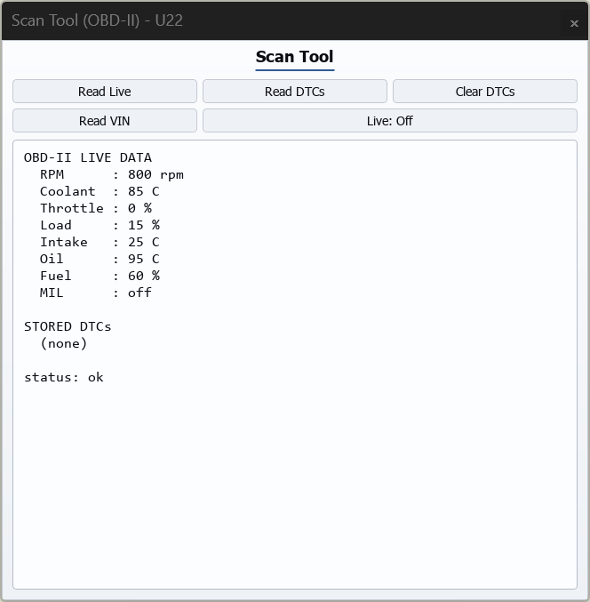
The Scan Tool popup with its read-live, read-DTCs and clear controls.
Device: SCAN_TOOL
Models a workshop OBD-II / UDS diagnostic tester that interrogates the diagnostic-capable ECUs on the bus.
It sends functional requests (0x7DF, or 29-bit addressing when selected) and reassembles the per-ECU responses (0x7E8 upward) over ISO-TP. The popup has buttons to read live data, read stored DTCs, clear DTCs and read the VIN; TARGET_ECU selects which responder to query. It can also drive the UDS SecurityAccess exchange with the immobiliser (see CAN Security).
Example
With an Engine ECU misfire active, point TARGET_ECU at the engine and click Read DTCs to retrieve P0300, then Clear DTCs to confirm it clears.
Diagnostic Multiplex
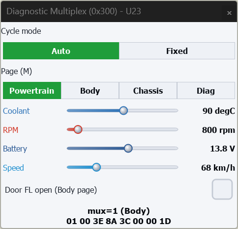
The Diagnostic Multiplex popup with the page selector and the live multiplexed-byte readout.
Device: DIAG_MUX (aliases MUX_NODE)
A teaching node for multiplexed messages: a single identifier whose payload means different things depending on a selector byte, the pattern real networks use to fit many low-rate signals into one frame.
It transmits a single message on 0x300 whose first byte selects one of four pages (Powertrain, Body, Chassis, Diagnostics); the remaining bytes are reinterpreted for each page, and a counter byte acts as a heartbeat. The popup selects whether the page cycles automatically or is held fixed, chooses the page, and shows the live bytes. Because the analyser has no built-in concept of a multiplexor, this node is used to teach reading a multiplexed frame by hand.
Example
Set the node to cycle automatically and watch the same 0x300 frame change meaning each period as the selector byte steps through the four pages.
Mystery Node
Device: MYSTERY_NODE
A teaching node for reverse-engineering exercises: it behaves exactly as one of the other models but ships with no popup and no database, so its identity is hidden.
A VERSION property (set by the tutor to an opaque code) selects which real model it impersonates; on the bus it produces that model's traffic, but with the popup suppressed and no .dbc loaded the student must recover its message format from the wire using the analyser.
Example
The tutor sets a hidden VERSION code; the student captures the unknown frames on the analyser, deduces the signal layout, and writes a .dbc to decode them.
Security Nodes
Two further models turn the bus into a security teaching bench: an Attacker that spoofs, replays and floods the bus, and an Intrusion Detection monitor that catches it. Because they are a self-contained unit with their own defences (authenticated messaging and access control), they are documented together under CAN Security.
Fault Injection and Diagnostics
Every node accepts the common FAULT_MODULE property described in Common Conventions, and each popup carries a fault-inject panel that arms the same faults live while the simulation runs, so a fault can be introduced at a chosen moment. A red banner marks a faulted node, and, where a node is diagnostic-capable, the fault raises a diagnostic trouble code that a Scan Tool can read. The node-level faults and the codes they raise are:
| Fault | Trouble code | Effect on the bus |
|
MUTE |
U0100 |
The node stops sending its messages but still acknowledges traffic. |
|
DEAD |
U0140 |
The node goes completely silent, neither sending nor acknowledging. |
|
BUSOFF |
U0073 |
The node drops off the bus as if its error counter had overflowed. |
|
STUCK |
per node |
The payload freezes at its last value; the code is the node's own rationality code. |
|
GARBLE |
U0401 |
The payload is corrupted, breaking any checksum, to model invalid data. |
|
DROPOUT |
U0100 |
The message comes and goes intermittently. |
|
OFFRATE |
P0607 |
The message is sent at the wrong period. |
|
WRONGID |
U0010 |
The node transmits on the wrong identifier. |
|
FLOOD |
none |
The node babbles at high rate, starving other traffic; the victims raise the codes. |
A worked fault-finding sequence, from injecting a fault to reading and clearing the code, is given in CAN Examples.
See Also
These behavioural nodes are designed to be used with the bus instrumentation and the controller and transceiver parts:
- The CAN Bus Analyser captures, decodes, sends and injects faults on the bus the models share.
- CAN Examples works through monitoring, firmware, fault injection and diagnostics step by step.
- CAN Security covers the attacker, the intrusion detector and the authentication and access-control defences.
- A CAN transceiver (for example MCP2551) and, where a controller is required, an MCP2515 or MCP2518FD are how a student's own MCU joins the same bus as these models.
A typical sample design places one student MCU and a handful of these behavioural nodes on a single bus with the analyser attached, so the student writes firmware for one ECU against a realistically busy network.