TUTORIAL 1: BLINK AN LED
Introduction
This tutorial is a short introduction to designing, developing and deploying a project with IOTBuilder. We've made the appliance as simple as possible to concentrate on the workflow from starting Proteus to controlling your Arduino Yun from your mobile phone.
This tutorial also assumes that you are familiar with flowchart programming with Visual Designer. If not, we recommend that you work through the tutorials in the Visual Designer reference manual linked below.
See Also:
Terminology
We refer to the appliance as the hardware being designed. This is 'virtual hardware' on the schematic during simulation and then physical hardware when deployed. In this tutorial, it is therefore the Arduino Yun plus any sensors, shields or breakout boards wired to it.
We refer to the controller as the device sending commands to the appliance. In the context of this tutorial this will be the front panel during the simulation and debug phase and the mobile phone or tablet when deployed.
Design Process
The workflow from project start to working product involves several distinct steps as shown below but the order is fairly flexible. We'll walk through the process in the following topics.
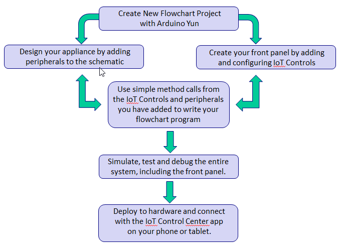
Creating an IoT product with Arduino Yun and IoT Builder.
Project Setup
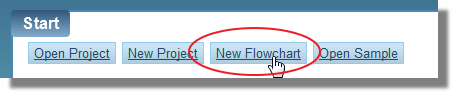
Launch the New Flowchart Wizard from the home page in Proteus, specify your name for the project and the folder which you wish to save into.
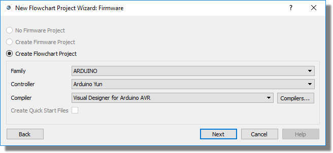
On the next screen we need to create our flowchart project. This creates the firmware which we will be using for the Arduino Yun controller in our connected appliance. This should look like the following:
We'll get a configuration summary page and can can then finish to setup the project.
You should now have two tabs open, one for a schematic in which an Arduino Yun has been placed and the second in Visual Designer in which the normal skeleton program constructs for Arduino have been placed.
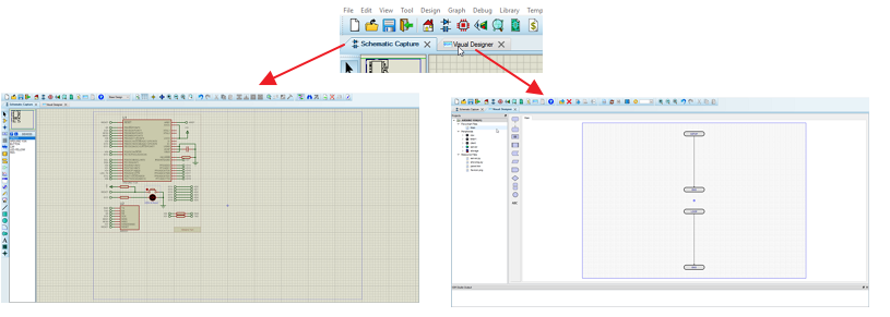
Correct Setup Complete.
Design the Front Panel
The front panel is the control interface to our appliance. It needs to contain the elements we need to send commands to the appliance and it contains the elements we need to display data sent from the appliance.
Since this is our 'hello world' project, we are going to turn an LED on and off from a button control on our front panel. We add internet of things controls either from the Project Menu in Visual Designer or by right clicking on the Arduino Yun text on the project tree.
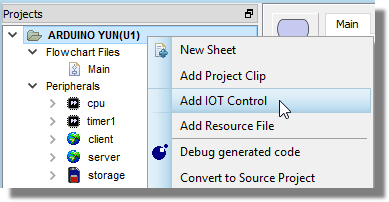
From the resulting dialogue form we need to choose a button and also a number of elements. In our case we need only one button but you could choose to have several elements in a radio button type situation. Select which theme you would like to use:
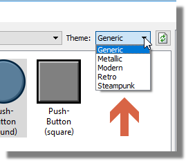
In our case we will be using the Generic single Round button
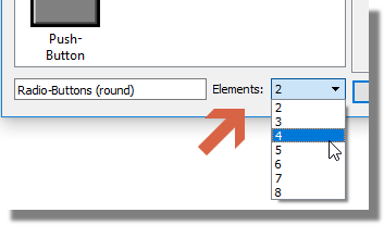
There are two options depending on the number of buttons required on your controller. A Single button (Push-Button Round/Square) or a set of button elements or a set number of buttons (Radio-Buttons Round/Square). If you select Radio-Buttons option, the elements dropdown box will be enabled for you to select the number of elements (buttons) required:
Our themes use what we call Auto Lamp which is a property of the push button control. When this is set to True, it means that the light on the button will automatically come on when it's clicked, no matter wether there is code associated to it or not. This is graphical / aesthetics only, and nothing to do with the programming. More information is available here
Note the theme selector towards the top right of the dialogue. This allows you to style your front panel in different themes such as retro, steampunk, modern, classic, etc.
After we add the button, notice that several changes have occurred in the Project Tree. We now have an IoT Control (our button) at the bottom and also an IoT Panel and a couple more resource files. Double click on the Panel in the project tree to open in the editing window:
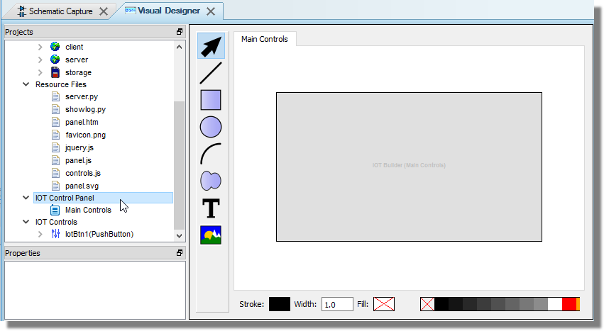
The Editing Window is now showing what will be the user interface for our appliance. By default, it is set to a mobile phone size but you can change this by right clicking on the front panel in the project tree and choosing the panel settings option from the context menu.
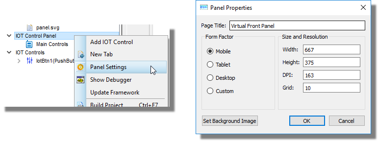
You'll find a list of phone and tablet values here: https://mydevice.io/devices/ . The width and height are the CSS Width and CSS Height in this table and the DPI is the physical PPI divided by the pixel ratio. An iPhone 7 for example is therefore 375x667 and the DPI is 326/2 = 163.
Here we've changed to a Galaxy S7, the phone that we will be using as our controller:
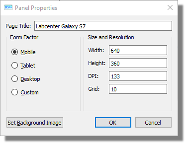
While you can change from a desktop browser to a tablet or a phone at any time it is really best to make a decision early on because any placed controls will not move if you resize the panel. This means if you resize the panel downwards (e.g. tablet to mobile) it is awkward to re-position all of the controls on the panel.
You can also change the background image. The default is a light grey box for simplification, however you may want to upgrade this to something which matches your theme. Simply download an image as a JPG or PNG file in to the Background folder and insert it using the Set Background option:
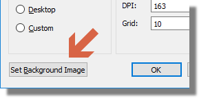
You can also change the background image. The default is a light grey box for simplification, however we have supplied several background images that match our themes. These are stored in a background folder (C:\ProgramData\Labcenter Electronics\Proteus 8 Professional\VSM Studio\controls\Backgrounds\..). Alternatively you may want to upgrade this to something which matches your theme. Simply download an image as a JPG, SVG or PNG file in to the Background folder and insert it using the Set Background option.
To place our button on the panel simply drag and drop from the button entry on the project tree to the panel.
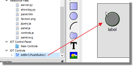
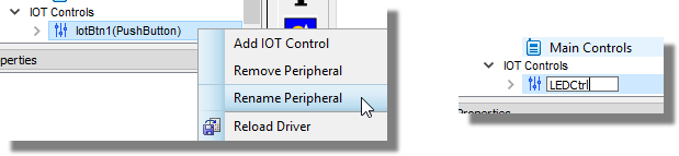
To rename the button right click on the item in the project tree and select rename peripheral from the resulting context menu.
We can edit almost anything we need to with the button via the property panel underneath the project tree. This shows all of the configuration properties available for the currently selected object on the panel. If the button is not selected (does not have a dashed box around it) click left on it once and then view the device properties.
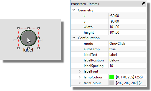
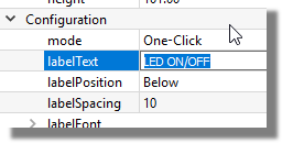
The property section for a button is fairly self-explanatory, consisting of a geometry section for accurate positioning and a configuration section. Here we can specify the type of button (single click is fine) and change the label to something sensible.
AutoLamp Property
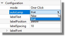
You can set an autolamp property on the IoT button. If so, it becomes a toggling button by default. However, if you turn autolamp off then you will need to use setLamp() on and off in the flowchart - the benefit of this being that it is hardware appliance driven rather than implicit in the GUI and therefore guaranteed to be correct. Alternatively if your program does not rely on an LED light and the on off will be for graphical purposes only, set the AutoLamp on the button to be on.
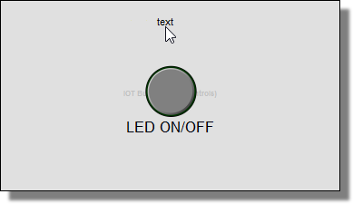
You can add title or graphics to the front panel directly from the primitives on the left hand pane. For example, to add a title we would first select text mode and then place the text indicator in approximately the right position on the panel.
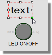
After placement, we stretch the text box to the size we want.
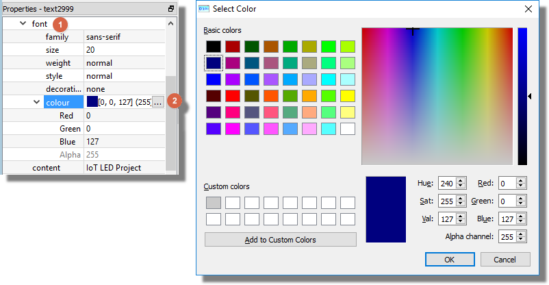
Finally, we can change the font, colour and text content in the property page. In the left hand pane, drop the Font option down and click on the colour.
.
If you have Radio buttons and wish to resize them, Right click on the button > Transfer > Restore Aspect Ration. More information is explained in the Guided Tour section.
If you require more than one front panel, you can add multiple tabs by right clicking on the 'Main Controls' in the project tree and select New Tab:
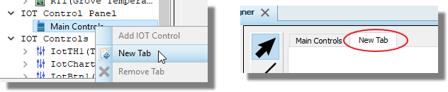
Writing the Program
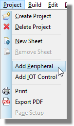
Now that we have a front panel and a placed control we can look at how this is going to interact with our appliance. Since the button is going to turn on an LED the first thing we need to do is to add an LED (whichever colour you choose) to our schematic (remember, think of the schematic as a virtual version of your hardware). We do this from the Add Project Clip command on the Project Menu.
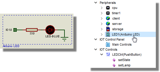
This will both add the LED (Blue, Yellow, Green or Red) to the schematic and it will appear in the project tree in Visual designer.
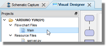
Now double click on the main flowchart page in the project tree to switch to the flowchart program.
What we need to do in the program is respond to the press of a button and either turn the LED on or turn the LED off. In Visual Designer we do this by creating an event that corresponds to the button click. You can do this really quickly by dragging and dropping from the button in the Project Tree as shown below.
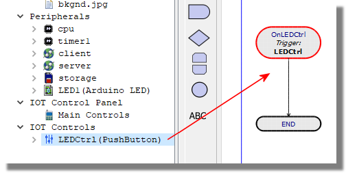
This is a shortcut which adds an event and then specifies it to respond to a button press interrupt.
What this means is that each time this particular button is pressed code execution will enter this routine. What we do when this happens depends on whether our LED is currently on or off. Drag and drop from the LED peripheral onto the flowchart and place the decision block in the new event.
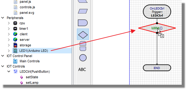
This is actually quite a powerful shortcut. When you drag and drop from the actual peripheral (rather than one of it's methods) you will get what we call the sensor function for the peripheral. In the case of the LED this is a decision that splits on whether the LED is on or off. You'll find more about sensor functions in the Visual Designer help file.
Now that we have a test for whether the LED is on or off all we need to do is turn it on when it is off and off when it is on. Expand the LED in the project tree and then drag and drop the off and on methods into the appropriate places.
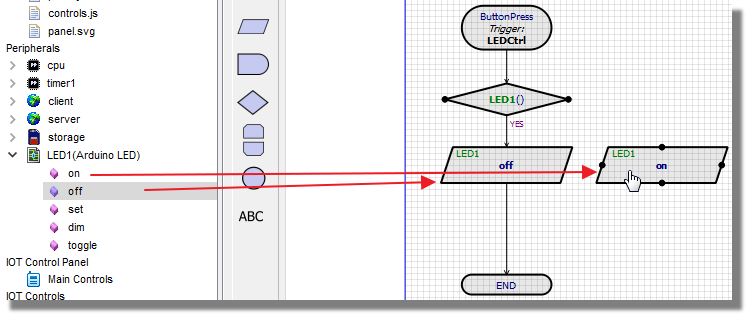
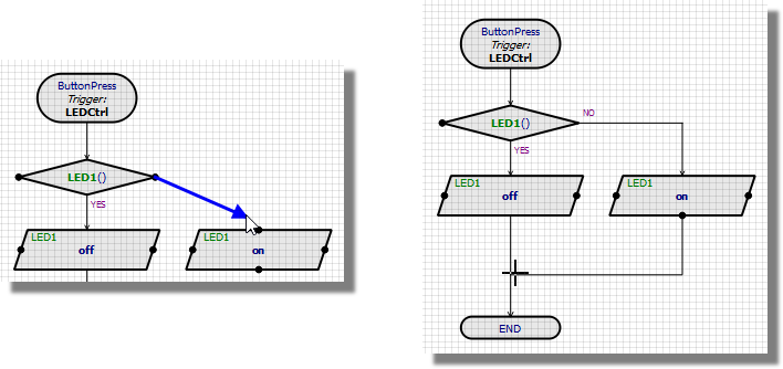
Finally, we'll need to place a couple of extra wires to connect up the ON state.
As a final touch, we'll add the front panel indicator when the led is on and off. This amounts more drag and drop placement, this time of the setLamp method from the project tree as shown below.
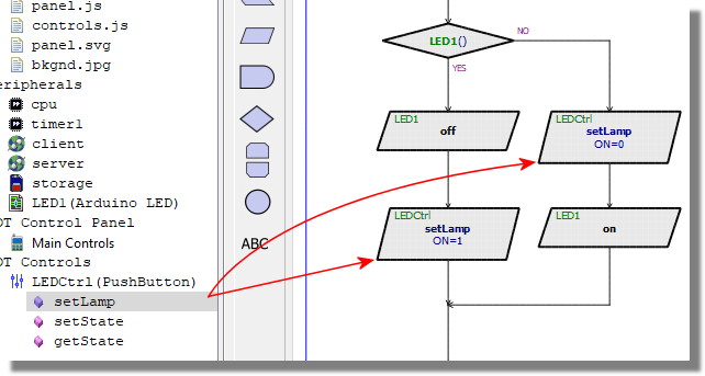
That's actually it - five flowchart blocks to toggle an LED on an Arduino Yun from a mobile phone ! Next we'll look at how we can simulate and test.
Simulate and Test
As a quick test that we haven't made any mistakes we can press the play button to simulate the system.
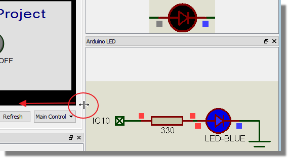
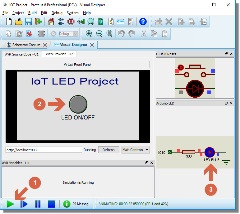
When the simulation is running on our virtual hardware we will end up with the front panel in the main section of the screen and any active areas of electronics on the right hand side. We can drag these out to suitable sizes - in our case to make the LED easily visible.
All that remains is to press the button and then wait to see if the LED turns on and then press the button again to turn the LED back off.
Let's assume however that something wasn't working and that we had to investigate. We'd start by pressing the pause button to halt the simulation.
Next we'd set a breakpoint somewhere in our flowchart. In our example, let's do that at the method call to turn the LED on.
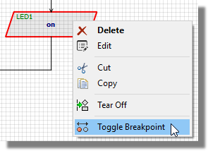
Now we run the simulation and press the button on our panel. The simulation will pause automatically when it hits our breakpoint.
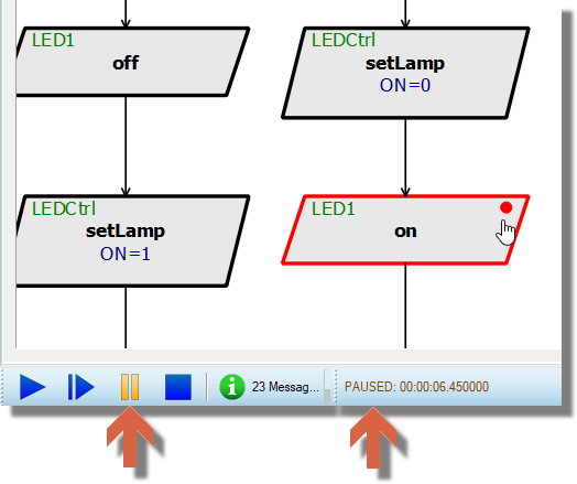
We can then use the step commands to single step debug our flowchart while watching it's effect on the circuitry. In our trivial example a single step will turn the led on.
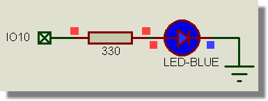
Another single step will illuminate the lamp indicator on our front panel
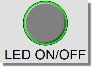
When we've finished simulation and we've confirmed everything is working as intended we can proceed to deployment.
This is of course as simple a test case as it's possible to get and there isn't a lot that can be done in terms of debugging. You'll find more coverage in other tutorials and in the Visual Designer reference documentation.
The App
The free IoT Controller app is the easiest way to get the front panel onto your mobile device.
- If you have Android device you can download the APP from Google Play. Search for Proteus IOT Builder and click on install, It's free!
- If you have an iOS device you can download the APP from Apple Store. Search for Proteus IOT Builder and click on install, It's free!
The app serves as a host for the front panel you create and also helps with discovery. The discovery is done by the Bonjour utility / Driver. This utility is present on many machines but you can launch the installer directly from the Labcenter Program group on the Start Menu. Now that you have the app you can control your running IoT builder simulation from your app as follows:
1. Make sure your mobile or tablet is on the same wifi network as your PC is on.
2. Start the running simulation in Proteus, then start the app on your phone.
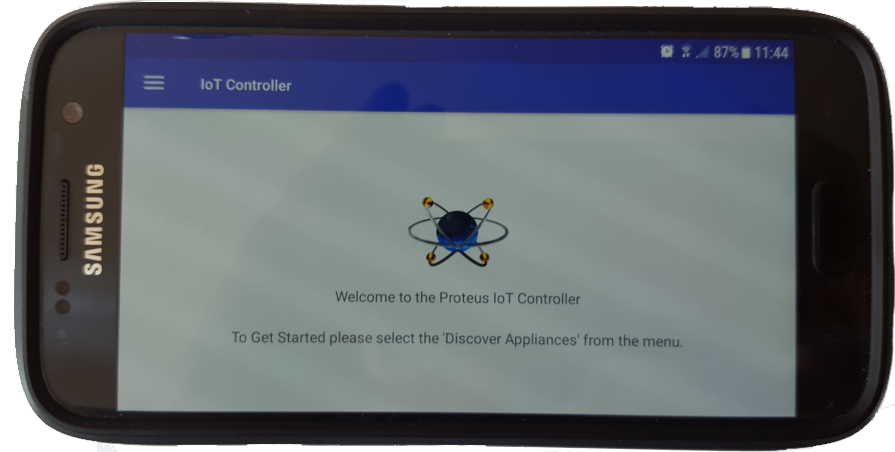
3. The app will open and you will see the following:
4. Click on the menu option at the top left and select Discover Appliances. Find Virtual Front Panel and select it with your finger.
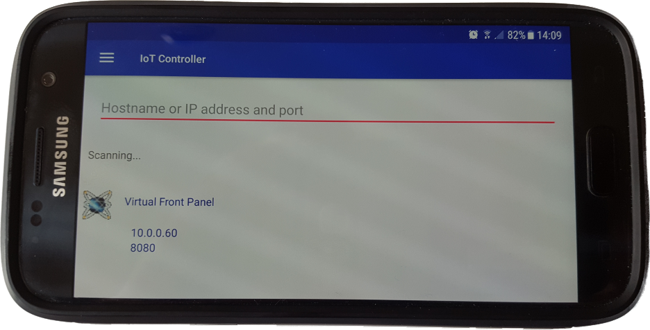
To change the name of the panel, go to Panel Settings (right click on Main Controls in the project tree) in Proteus and change the Page Title.
5. The Running simulation should automatically appear in the App:
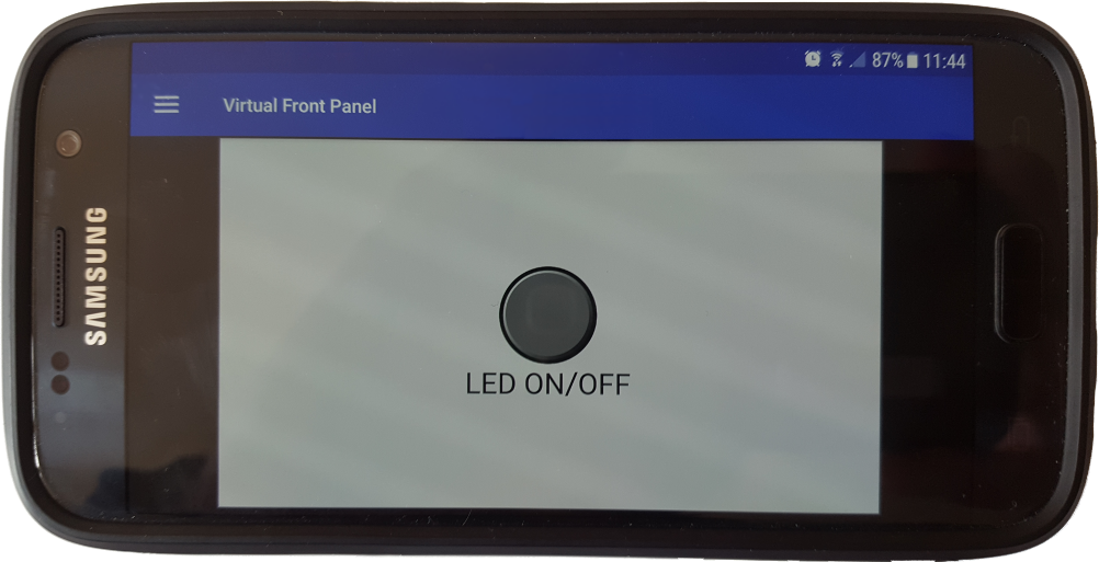
6. A Message will appear in the Front panel in Proteus that says the following:
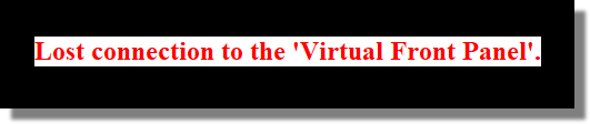
This is because it is now being displayed on the controller.
Obviously this won't work if your computer doesn't have wifi or isn't on the same network as the phone.
7. Press the button on your phone, the led will come on in the simulation and the indicator lamp will light up on your phone app.
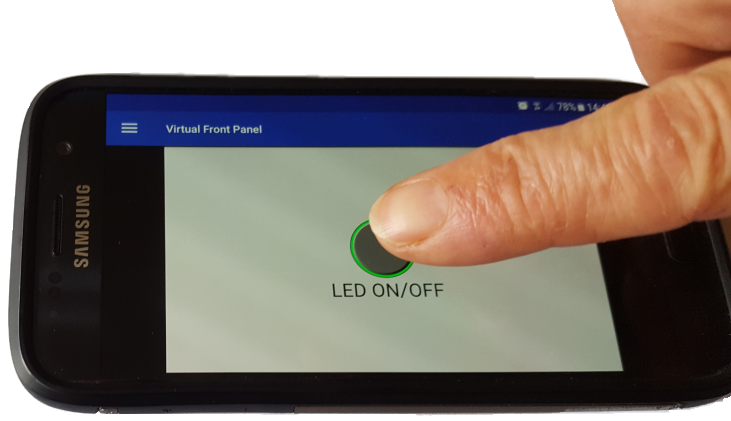
Which results in the LED on the schematic turning on:
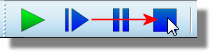
8. Stop the simulation and/or disconnect when you are finished. Closing the App on your controller will not end the simulation on the PC, you will need to press the STOP button in Visual Designer.
More information is in the Mobile App help section The Mobile App
Programming
Now that we have the app and our mobile control center is working the final step is to program the physical hardware with our firmware. We can do this either through wireless SSH if your computer has wifi or through USB if not. The process is basically the same in either case. For this example we will do this wirelessly.
The Arduino Yun Shield (mounted on an Uno or Mega) cannot be programmed via USB because the serial connection is already in use. The Yun board can be programmed either via SSH or via USB.
1) Switch on the Yun by plugging the power supply in (if you are programming via USB make sure it is plugged in, the USB cable to PC can act as both power and programming).
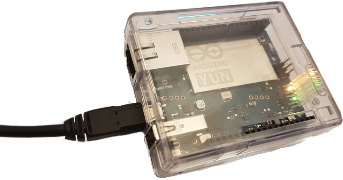
2) After waiting for about 30 seconds for the YUN to boot, Set your PC and your controller to be on the ARDUINO wireless network:
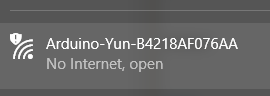
This will take you off the internet but you won't need it for this exercise.
3) Launch the project settings dialogue in Visual Designer.
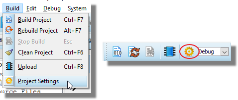
4) If you are programming by WiFi select the YUNSSH programmer and the SSH interface. Your Arduino Yun should be discovered automatically and shown in the host dropdown combo box.
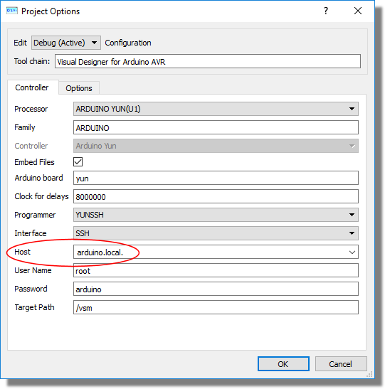
The default name of the Yun has the mac address appended at the end and you should find this written on a sticker on the back of your board.
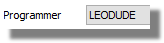
If you are programming by USB you need to select the LEODUDE programmer, the COM port and the speed of the arduino. The YUN is 57600 by default.
Now click on the Firware icon to upload your program to the Yun:
More on programming via wireless, USB and ethernet is explained here.
How does it work ?
If you are programming by SSH then the firmware and resources (webserver, front panel graphics etc.) will arrive at the Atheros chip. This will automatically run AVRDUDE and program the firmware onto the AVR processor via the ICP interface.
By contrast, if you are programming via USB then the bootloader on the AVR will be used to pass all of the resources across the data bridge to the Atheros chip and then AVRDUDE on the PC will be used to program the firmware onto the AVR processor. This method can be significantly slower if the front panel design is reasonably complex.
In either case, you will end up with firmware, webserver and front panel deployed as shown below.
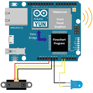
Flowchart program on AVR, webserver and front panel graphics on Atheros.
See Also:
Controlling the Hardware
Assuming that we have an LED wired on the real device to the same pin (IO10 in our case) and that the Yun is powered on then the first step is simply to use our app to discover the real Yun in the same way we did earlier for the simulated Yun.

Now we can press the button on our phone and control the LED on the real hardware, exactly as we did in simulation
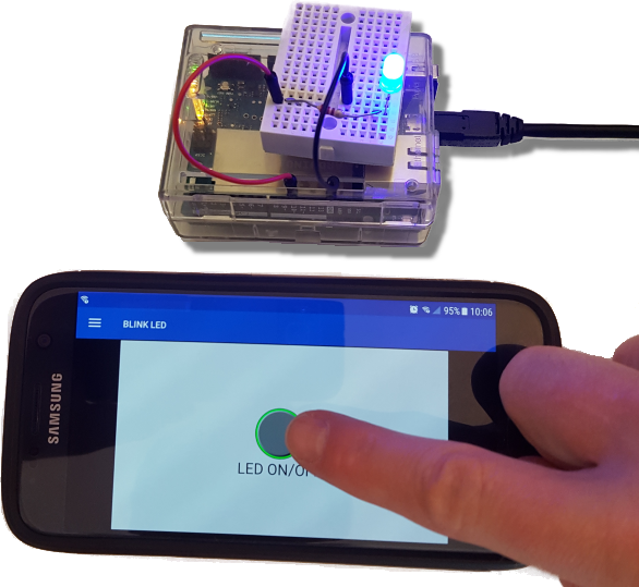
That completes the basic tutorial and hopefully shows just how simple it is to get things working with IoT Builder. For something a little more useful/realistic it is also well worth working through the Temperature Logger tutorial.
See Also :