INTERACTIVE AUTO-ROUTING
Overview
Working with the router in interactive mode maximises the flexibility you have over the routing process. It allows you to route parts of the board easily and gives you full control over the order and priority of routing tasks. You do however need to have an understanding of the basic command set and of the different routing phases in order to maximise the use of this mode of operation. It is therefore most likely to be of use in more complex designs, or for users comfortable with directing the flow of the router.
If you have invoked the autorouter in interactive mode you will see that a command window is launched at the bottom of the Editing Window. It is important to understand that at this point you are in autorouting mode and therefore that any attempt to change the layout will exit the routing mode before applying your commands. Similarly, if you switch modes (for example, to component or track mode) then you are implicitly leaving autorouting mode and Proteus will therefore remove the command window accordingly.
Basically, when you have entered the interactive routing mode you can:
- Type routing commands to control the autorouter.
- Use the mouse to select an area or net which you wish to route.
- Use the Object Selector to select a net.
- Use the mouse or keyboard to navigate the layout in the normal way.
Other operations will cause the routing mode to exit before taking place.
Leaving the Session
To end the session deliberately, press ESCAPE in the command window. Proteus closes the console, commits the routes the session produced to the layout permanently and runs a design rule check on the result.
Aborting a Command
Pressing ESCAPE while a routing command is actually running aborts that run instead. Proteus reports that routing was aborted, and what happens to any conflicts left behind depends on the Conflict Handling setting on the autorouter dialogue form.
Specifying Nets
By default, any commands you type in the command prompt will act on the entire board. For example, if you type route 20 then twenty routing passes will occur on the entire board. It is quite common however to wish to route a particular area of the board (e.g. around a small pitch SMT footprint) prior to the global routing process. You can do this in Proteus simply by dragging a selection box around the area of the board that you wish to route.
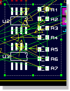
Selecting an area to route
Having created the selection area you then have two options:
- Limit the selection only to nets entirely enclosed by the selection area.
- Extend the selection to all nets where a connection on that net is partially enclosed by the selection.
You can toggle between these two options via the track selection mode button on the Selection Filter. Its two states are Track Selection Mode: Enclosed, which gives you the first option, and Track Selection Mode: Intersecting, which gives you the second.

Track selection mode
The selection box picks the nets to route; it does not confine the routing to the box. Whichever way you make the selection, the router works on complete nets, so a track belonging to a selected net may well be routed well outside the area you dragged.
Alternatively, you may wish to limit the initial routing to affect only a specified net. You can do this by simply clicking the mouse on a pad on that net. This will highlight all of the ratsnest connections on that net, and any subsequent routing commands will apply only to the selected objects.
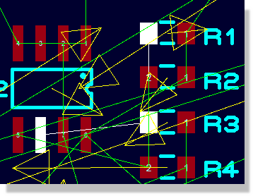
Single net selection
If a selection exists the router commands will be limited to operating only on the selection. This means that, if you want to revert to routing globally, you need to click the mouse on an empty area of the layout to deselect all currently selected objects.
Routing Phases
In interactive mode you drive the router by indicating what you want to route (via selection) and then typing commands to direct the router's progress. In order to successfully do the latter it will be useful to look at the three phases of a typical routing schedule.
Preparation
This is the first phase where commands are issued to handle particularly difficult routing objects. A good example here is the fanout command, which should be used before routing to make access to fine pitch SMT footprints easier.
Routing
This is the main phase and we typically use both the route and the clean commands here. It is important to remember that the router is adaptive, so if you do not reach completion, repeat the process; you are not doing the same thing again.
Tidy Up
Once we are finished with the routing phase we enter commands to tidy up the board. This is where we might use the filter command if we did not reach completion, and where we would use the recorner command to minimise track lengths or avoid solder traps.
A good example of the type of command set that you would use for a typical routing exercise is the basic schedule described under creating routing scripts.
Command Syntax and examples of usage can be found in the command reference.
Example: Routing in Interactive Mode
This example describes how you would typically route a board in interactive mode, assuming that you have configured design rules, layer sets and net classes through the Design Rule Manager.
To route a layout interactively
- Launch the router in interactive mode.
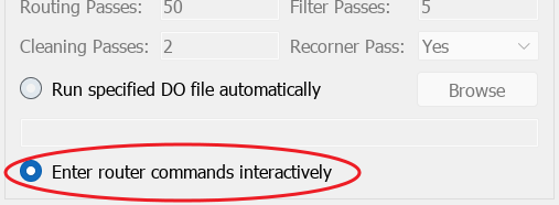
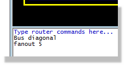
- The preparation phase consists of the bus command followed by the fanout command to provide access to fine pitch SMT parts.
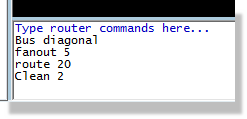
- The initial routing phase then consists of the route command (single parameter for number of passes) followed by the clean command to tidy up.
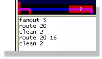
- Subsequent routing phases consist of the route command (two parameters: number of passes and start pass) followed by the clean command to tidy up.
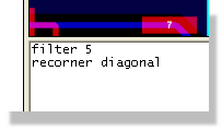
- Once we are finished routing, the tidy up phase consists of the filter command (if we did not achieve completion) and possibly the recorner command for solder trap avoidance.
The router is adaptive so re-using the same route commands in subsequent passes does not simply repeat the same routing process.
Example: Routing a Net on a Particular Layer
Proteus provides a User Interface for this via the design rule manager (Technology menu) where you can specify the routing layers for any given net class. However, you can directly instruct the router to do this in interactive mode. The layers are identified for routing purposes as follows:
| Layer Name | Designator | Layer Name | Designator | |
| Top Copper |
TOP |
Inner 8 |
I8 |
|
| Inner 1 |
I1 |
Inner 9 |
I9 |
|
| Inner 2 |
I2 |
Inner 10 |
I10 |
|
| Inner 3 |
I3 |
Inner 11 |
I11 |
|
| Inner 4 |
I4 |
Inner 12 |
I12 |
|
| Inner 5 |
I5 |
Inner 13 |
I13 |
|
| Inner 6 |
I6 |
Inner 14 |
I14 |
|
| Inner 7 |
I7 |
Bottom Copper |
BOT |
To route a net on a particular layer
- Launch the router in interactive mode.
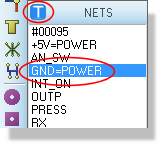
- Tag the net (e.g. GND) by selecting it in the Object Selector and then clicking on the T button at the top.
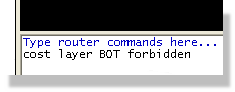
- Use the cost command to forbid routing on one or more layers.
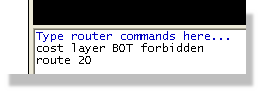
- Use the route command to route the net on the remaining layer.
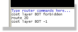
- Use the cost command again with value -1 to reset to default.
Note that restricting the layers available for routing makes achieving completion much more difficult.
Example: Protecting existing tracking
To protect tracking when routing interactively.
- Launch the router in interactive mode.
- Use the protect command with all wires prior to routing.
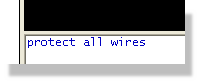
- Use the unprotect command when you are finished.
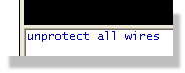
The lock command can be used instead of the protect command if you want to prevent the router connecting to tracks already placed as well as prevent the tracks being moved/deleted.
Example: Controlling Fanout on SMT Chips
Fanouts are escape wires from SMT pads which then allow the router to make connections. Typically, the fanout is one of the first commands to be executed when routing but interactive mode gives you far more control over what happens in this phase.
To execute the default fanout
fanout 5
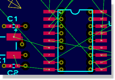
Fanout 5, where the vias are inside the IC
To force fanouts to be outside the IC
fanout 5 (direction out)
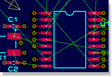
Now note that the vias are outside the IC
To allow via sharing on a fanout
fanout 5 (via_share on)
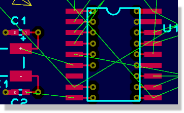
Note that C1 and X1 now share the same via
Example: Setting the Maximum Number of Vias for a Track
To specify a maximum of two vias to be used when routing the GND net.
- Launch the router in interactive mode.
- Tag the net (e.g. GND) by selecting it in the Object Selector and then clicking on the T button at the top.
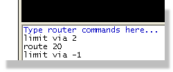
- Use the limit via 2 command to limit the number of vias.
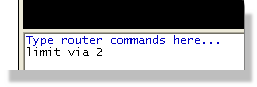
- Route the net.
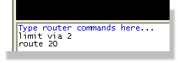
- Reset to defaults by using -1 with the limit command.