PRINTER OUTPUT
Overview
Output through standard Windows device drivers is performed using the Print Layout command on the Output menu. The command opens the Print Layout dialogue form, from which you choose the printer, the layers to be printed, the colour set, the scaling and the position of the output on the paper. Context sensitive help is available on all fields within the dialogue form.
Specifying a Printer Device
The printer is selected inside the Print Layout dialogue form itself. The Printer & Output Device group at the top of the form shows the current printer name, its type and the paper it is set to use; press the Configure Printer button to change the device or to alter the driver's own settings. Your choice is remembered for future sessions.
Choosing a Layer Set for Printing
The left hand side of the dialogue form controls what is printed. The Mode combo at the top selects the type of output: Normal Artwork, Assembly Plot, Drill Plot or Testpoint Plot. Assembly Plot produces an assembly drawing, while Drill Plot and Testpoint Plot produce drill and testpoint drawings respectively. Each mode remembers its own layer selection, so switching between them does not disturb the others.
Below the Mode combo the layers are presented on three tabs: Copper holds the top, bottom and inner copper layers; Data holds the assembly, mechanical, occupancy, keepout and illegal layers; Other holds the silk screen, resist, paste, edge, slot and drill layers. Only the layers that are meaningful for the selected mode are enabled.
Each layer has three states rather than two, and clicking its checkbox cycles through them:
- Automatic, marked with an asterisk symbol. The layer is included or excluded according to whether it is in use on the board, so the selection keeps up with the design as you work on it.
- Manually on, marked with a pencil symbol and ticked. The layer is always printed, whether or not it is in use.
- Manually off, marked with a pencil symbol and cleared. The layer is never printed, even if it is in use.
The legend at the bottom of the selector repeats the meaning of the two symbols. The Quick Select group applies a change to several layers at once: choose For Current Tab or For All Layers in the combo, then press Turn On or Turn Off to set those layers manually, or To Auto to hand them back to the automatic selection.
If you are printing several layers that will overlap on the paper it is usually better to print one layer per page, which you do by ticking Separate Pages? in the Options group.
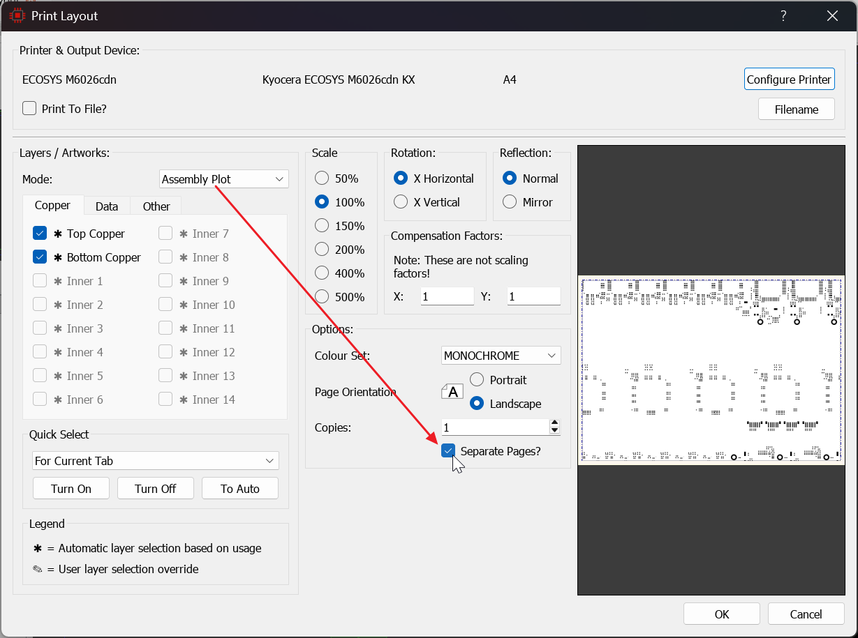
Choosing the print mode and the layers to be printed
Choosing a Colour Set for Printing
The Colour Set combo in the Options group determines the colours used for the print job. Three sets are provided as standard: MONOCHROME for black and white printing, BLACK_PAPER and WHITE_PAPER. You can create your own colour sets through the Edit Layer Colours/Visibility command on the View menu (CTRL+L) and these will then be available both on screen and in this combo for printing.
Scaling, Rotation and Reflection
The Scale group prints the board at 50%, 100%, 150%, 200%, 400% or 500% of its true size. Rotation prints the board with its X axis running horizontally or vertically across the page, and Reflection prints it either Normal or Mirror, which is what you need when printing artwork onto film. Page Orientation switches the paper itself between Portrait and Landscape, and Copies sets the number of copies to be printed.
The Compensation Factors group carries separate X and Y values which stretch or shrink the output very slightly to compensate for the behaviour of a particular device or film.
The compensation factors are not scaling factors. Use the Scale group if you want to print the board larger or smaller; use compensation only to correct a measured dimensional error in the finished output.
Print Preview
The print preview appears on the far right of the Print Layout dialogue form and displays the position and size of the board relative to the specified paper size. It updates live as you configure the dialogue form, so the effect of a change to the scaling, the colour set or the layer selection is visible immediately.
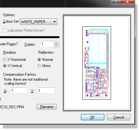
Print preview in the Print Layout dialogue form
Positioning the Output
You can adjust the position of the printed area by left depressing the mouse on the print preview and dragging the board to the desired position. Alternatively, right click on the preview and choose one of the five preset positions from the context menu: Position at Center, Position Top Left, Position Top Right, Position Bottom Right or Position Bottom Left.
Changing the scale or the page orientation re-centres the board on the page, so set those first and position the output afterwards.
Printing to a File
Tick Print To File? if you want the printer driver to write its output to a file rather than send it to the device, then press the Filename button to choose where the file is written. This is occasionally useful for submitting a job to a bureau that works from printer files.
Repeatable Print Runs
Printing from this dialogue form is a manual operation, so a set of prints that you produce at every revision has to be set up by hand each time. Where that is the case, use the Output Job Manager instead. An output job profile stores the layers, colours and scaling for each print or export task and runs the whole set in one operation, which both saves time and removes the risk of forgetting a layer.
See Also: