MCAD OUTPUT
Overview
It is increasingly common now to export a PCB fileset for import into mechanical cad software such as Solidworks or Autodesk. This enables case design and review of mounting and ventilation considerations.
Proteus includes full support for both AP203 and AP214 STEP formats as well as the older IGES and STL formats.
The command is Output Menu > Generate 3D M-CAD File, which opens the 3D M-CAD Output dialogue. This has two tabs: MCAD Output holds the settings described below, and Log reports the result of the export.
The dialogue names the four formats as follows:
- STEP AP203 (.STEP)
- STEP AP214 (.STEP)
- IGES (.IGES)
- STL (.STL)
AP214 is the usual choice for mechanical CAD interchange; AP203 is the older geometry-only variant. The remaining controls are File Name, which is the filestem for the exported file, Folder, which is the destination directory, and Automatically open output folder.
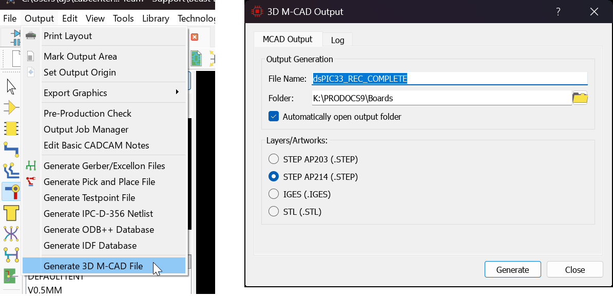
Generating MCAD data.
Unlike the CADCAM, IDF, ODB++ and Pick and Place forms, the MCAD form does not accept field codes in its File Name and Folder fields. Type the values you want directly.
You can also elect to embed the MCAD files into the project file itself so that it can then be shared between computers.
Pre-Requisites
In order to export MCAD data for the PCB, we need to have mechanical models for the parts on the board. This is especially relevant for critical parts such as tall radial electrolytics or connectors. The process for adding mechanical data is covered in depth in the 3D Viewer chapter of this document but basically the requirement is to have an mechanical entry in the 3D Models dialogue form. This can be a STEP or IGES file downloaded from the internet (E.g. www.3dcontentcentral.com) and placed in the MCAD directory of your Proteus installation, or it can be a simple scripted model defining height and pin types for the part.
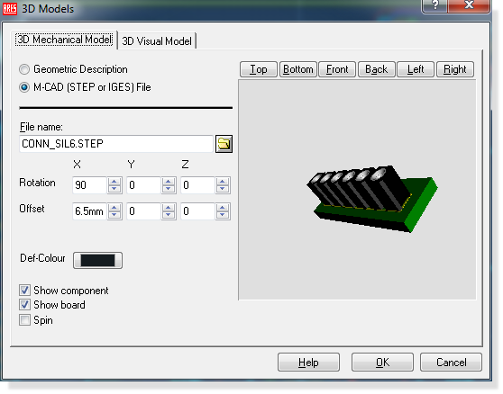
Specifying an MCAD model for a part.
Normally, you would add MCAD data via the Make Device command to ensure that it is then available for all future projects.
Rules for MCAD Export
- A part that is not fitted in the currently selected Assembly variant will not appear in the MCAD output.
- The board edge and all holes in the board will be exported.
- If a 3D mechanical model exists for a component then that component will be exported.
- 3D Visual models are ignored completely for MCAD Export.
- The board and feature thickness is taken from the Set Board Properties command on the Technology menu.
- The Log tab will warn of parts with no 3D model.
See Also: