MISCELLANEOUS
The Sheet Border
When a new sheet is created either as the first sheet of a new design, or by using the New Sheet command, it starts off at the size currently specified via the Set Sheet Sizes command. The extent of the sheet is shown by a dark blue sheet outline but this in itself will not actually appear on hard copy.
If a sheet border is required on the final output, you must place a graphics box (or whatever) over the sheet outline or use one of the pre-supplied templates.
The Set Sheet Sizes command, on the System menu, is worthy of further discussion since it serves two distinct purposes:
- To change the paper size for the current sheet, you simply invoke the command and click on the button for the required sheet size.
- To re-define the dimensions of a paper size, highlight the appropriate data entry field(s) and key in the new dimension(s). If you change the dimensions of the current sheet size, this will affect the current sheet immediately but not any other sheets in the design. To affect these, you must invoke Set Sheet Sizes and click OK for each sheet in turn.
The Set Sheet Sizes dialogue form allows you to define the sizes of five standard sheet sizes (A4 through to A0) as well as a non-standard size and to select which one is the size if the current sheet.
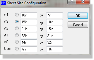
The Set Sheet Sizes dialogue form
For each sheet size (A4-A0 and user) there are two edit fields. The left field defines the width (x-dimension) and the right side defines the height (y-dimension). Whenever the schematic loads a sheet that does not match any of the standard (A4-A0) sheet sizes it places the dimensions of the sheet into the User field and sets that to be the default sheet size for the loaded sheet.
The default values for the standard sheet sizes should work for most printers but please note that all printers have ‘margins’ in which they cannot print: if you attempt to print something that impinges on the margins it will most likely not be drawn. The size of the margin where a printer cannot print varies between printers and the best way to determine it is to draw a sample design with a box that surrounds your chosen sheet size and then printing it. If one or more edges of the box do not appear on the printed output then your sheet size extends into the printer's margins and you should reduce it.
There is one more point to note about sheet sizes: every sheet in a design carries its actual dimensions with it in the design file. If a design is loaded into a schematic editor with a different sheet size configuration, this will not have any effect unless and until the Set Sheet Sizes command is used.
It is recommended that you either use an existing template or customise the size of a blank schematic and save it as a template. This is then re-usable for all future designs.
In order to use the component placement report you should either use one of our pre-defined templates or set the smart grid markers on a sheet border of your own making. More information here.
The Header Block
It is common practice to have on each sheet of a drawing a header block which shows details such as the design and sheet titles, the document, revision and page numbers, and the design's author.
In order that you have full control over how this information is presented, the header block is defined as a symbol library entry called HEADER. This was made in the usual way by placing graphics objects, tagging them and invoking the Make Symbol command. The significant thing is where, for example, the current design title is required, a text object with the string @DTITLE was placed and this is automatically replaced with the actual design title at display/print time.
The complete list of such keywords is shown below :
| Keyword | Description | SCHEMATIC | PCB |
|
@DTITLE |
The design title taken from the Edit Design Properties command on the Design Menu. |
✓ |
✓ |
|
@BOARD |
The name of the board you are currently working on, taken from the name supplied. Relevant only for multi-board projects. |
✓ |
✓ |
|
@STITLE |
The sheet title taken from the Edit Sheet Properties command on the Design Menu. |
✓ |
✗ |
|
@DOCNO |
The design document number taken from the Edit Design Properties command on the Design Menu. |
✓ |
✓ |
|
@REV |
The design revision number taken from the Edit Design Properties command on the Design Menu. |
✓ |
✓ |
|
@AUTHOR |
The design author, taken from the Edit Design Properties command on the Design Menu. |
✓ |
✓ |
|
@CDATE |
The design creation date - generated automatically in a fixed format. |
✓ |
✓ |
|
@MDATE |
The design modification date - generated automatically in a fixed format. |
✓ |
✓ |
|
@WS_CDATE |
The design creation date - generated automatically and formatted according to the Windows short format. |
✓ |
✓ |
|
@WL_CDATE |
The design creation date - generation automatically and formatted according to the Windows long format. |
✓ |
✓ |
|
@WS_MDATE |
The design modification date - generated automatically and formatted according to the Windows short format. |
✓ |
✓ |
|
@WL_MDATE |
The design modification date - generated automatically and formatted according to the Windows long format. |
✓ |
✓ |
|
@CTIME |
The design creation time - generated automatically and formatted according to the Windows time format. |
✓ |
✓ |
|
@MTIME |
The design modification time - generated automatically and formatted according to the windows time format. |
✓ |
✓ |
|
@PAGENUM |
The current sheet page number within the design. |
✓ |
✗ |
|
@PAGECOUNT |
The total number of sheets in the design. |
✓ |
✗ |
|
@PAGE |
The sheet number within the design expressed as X/Y where X is the sheet page number and Y is the total number of sheets in the design. |
✓ |
✗ |
|
@FILENAME |
The current design's filename. |
✓ |
✓ |
|
@PATHNAME |
The full path and filename of the current design file. |
✓ |
✓ |
|
@PAGESIZE |
The page / sheet size as set by the Set Sheet Sizes command on the System menu. This resolves to A4 through to A0, or to A through to E if you are working in a US locale. A sheet whose dimensions match none of the standard sizes resolves to User. |
✓ |
✗ |
|
@VARIANT |
The name of the currently active assembly variant. Can be used both on schematic (e.g. Header block) and on layout (e.g. Silkscreen text). |
✓ |
✓ |
|
@FILESTEM |
The project file name without its extension. |
✓ |
✓ |
|
@DIRECTORY |
The directory the project is stored in. |
✓ |
✓ |
|
@CUSTID |
Your Proteus licence number. |
✓ |
✓ |
|
@SNAME |
The module name of the current sheet. |
✓ |
✗ |
The Windows long and short date formats and Windows time formats are set using the Regional Settings or International applets in Windows Control Panel.
Note that the above keywords must appear at the start of a 2D text string and that the string should not contain additional text. For example, do not place strings of the form:
AUTHORED BY @AUTHOR ON @WS_MDATE
as these will not work! To achieve the above you need to place four strings along side each other (AUTHORED BY, @AUTHOR, ON and @WS_MDATE).
By use of the import bitmap facility, 2D graphics objects and such special text objects it is possible to define any kind of header block you want. In particular, you can incorporate your company logo into the header. Once defined, the header can be placed onto each sheet of the drawing like any other graphics symbol.
We strongly advise you, having created your header block, to place one on the Master Sheet and save as a design template. Please see the help documentation on templates for more information or run through the Tutorial.
Send to Back/Bring to Front
Sometimes several objects (especially Graphics) overlap and it becomes difficult to point at the one you want. By default, Proteus takes the most recently placed object, but you can re-arrange the order using the Send To Back and Bring To Front commands on the Edit menu, default keys CTRL+B and CTRL+F. Each command operates on the currently tagged objects.
You can also use these commands to order the draw order when creating new devices. For example, if you are creating a new op-amp symbol, you may need to send the op-amp body (the triangle graphic) ‘to the back’ in order to ensure its fill pattern doesn’t obscure the ‘+’ and ‘-’ input symbols, which of course, need to be ‘in front’.
Global Annotation
Proteus can automatically choose component references for all or some of the components in a design. This process is called Auto-Annotation.
The process is initiated using the Global Annotator command on the Tools Menu.
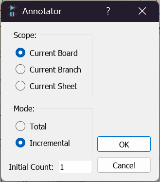
The Annotator dialogue form
The scope options are Current Board, Current Branch and Current Sheet. Current Board annotates the whole of the board you are working on, which in a multi-board project is not the whole project. Current Branch annotates from the sheet you are on downwards in the hierarchy, and Current Sheet annotates the current sheet only.
The Initial Count field defines the base annotation for the current sheet and sets this property for the current sheet. If you are operating in branch or board mode then any specified sheet offsets on other sheets will be honoured.
The mode options specify whether all parts should be re-annotated (total mode) or only un-annotated parts (incremental mode).
As with all dialogues in Proteus, comprehensive context sensitive help is provided for all the fields on the form. Use the question mark at the top right of the dialogue form to 'point and shoot' at a field for more information.
Keyboard Configuration
Proteus provides an interface for you to map the keyboard to a command set. This allows you to ‘bring out’ the functionality you commonly use according to personal preference. The Edit Keyboard Map dialogue form, accessible via the Set Keyboard Mapping command, is shown below (context sensitive help is available for all fields within the dialogue itself):
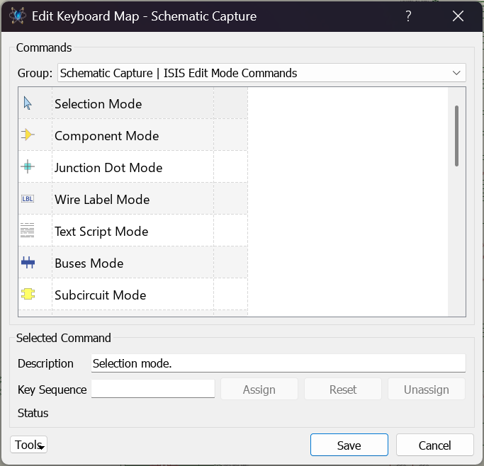
The Edit Keyboard Map dialogue form
The Commands section lists the commands, with a Group combo box for narrowing the list to one menu or context. Pick a command and its details appear in the Selected Command section below, where you can key a new accelerator into the Key Sequence field. Three buttons act on that one command: Assign gives it the key sequence you have entered, Reset returns it to its default sequence if it has one, and Unassign leaves it with no sequence at all.
The Tools button at the foot of the form opens a menu with three commands that act on the whole map: Reset to Defaults, Export to File and Import from File. Your changes are applied when you click Save.
Notes :
- Accelerators can use any combination of CTRL, SHIFT and ALT keys. For example, CTRL+X, CTRL+ALT+T, SHIFT+CTRL+1, etc.
- Reset to Defaults, on the Tools menu of the form, reloads all Proteus standard shortcuts. This will clear any custom configuration. It is not the same as the Reset button, which only affects the command you have selected.
- Some European keyboards have an ALT GR key (normally found directly to the right of the space bar). Where present this translates to be CTRL+SHIFT for the purposes of assigning keyboard shortcuts.
- If you assign an ALT accelerator that is used as a menu accelerator then you will no longer be able to accelerate the menu from the shortcut. For example, ALT+T by default expands the Tools Menu. If you assign ALT+T to the Tidy Design command then you would have to access the Tools Menu using the mouse.
- Some commands have keyboard assignments that cannot be changed. Goto Previous Sheet and Goto Next Sheet on PgUp and PgDown, and F1 for help, are examples, as are most of the commands on Maximised Graphs. Note that an assignment for these commands cannot be re-assigned to another command.
- If you assign a keyboard shortcut (e.g.CTRL+K) in the Application and then assign the same shortcut in a simulation popup window then the functionality executed by the shortcut is dependant on the focus at the time you use the accelerator. To avoid confusion we recommend you avoid multiple assignations of the same accelerator combination.
- When the NUM LOCK is on the keys 0-9 on the numeric keypad are distinct from the 0-9 keys on the main keyboard. For example, you could assign CTRL+0 up to CTRL+9 on the main keyboard as shortcuts to the Recent Projects list and on the numeric keypad you can assign CTRL+NUM-0 up to CTRL+NUM-9 to Goto Sheet 0-9.
- When the NUM LOCK is off keys 0-9 on the numeric keypad action their secondary functions and these functions are considered identical to those on the main keypad. The key for the number 5 on the numeric keypad has no secondary function when NUM LOCK is off.
- You can save your custom keyboard configuration with the Export to File command on the form's Tools menu. This allows you, for example, to port your keyboard configuration to another computer. Import from File reloads a configuration that has previously been saved.