PROPERTY DEFINITIONS
Introduction
A property definition tells Proteus what a named user property means. It carries a description, the kind of value the property accepts, a range or list of permitted values and a default. Where a definition exists, the property is presented on the Edit Component dialogue form as its own labelled field with a control suited to its type, rather than as a line of text in the property block, and the value the user types is checked before it is accepted.
Properties which are not known for a particular device, and all the properties of a device which has no property definitions at all, still appear in the textual property block as described in Object Properties. The scheme is thus backward compatible with old designs and library parts.
Creating Property Definitions
There are three routes to creating a property definition.
- The Device Properties page of the Make Device dialogue form, which is the route to use when you are building or editing a library part. The editor on that page is the Component Properties & Definitions control, and it is the same control that the System menu presents for the default definitions.
- The Bill of Materials property editor. Adding a field to the Bill of Materials creates a definition for you at the point you create the field. For example, if you add a field for Minimum Order Quantity (MoQ) to the BOM, you can then populate it with values per component and apply the changes back to the schematic, and your property definitions are updated with the specification for the MoQ property.
- The Physical Property creator, also in the Bill of Materials module, which writes a new definition directly.
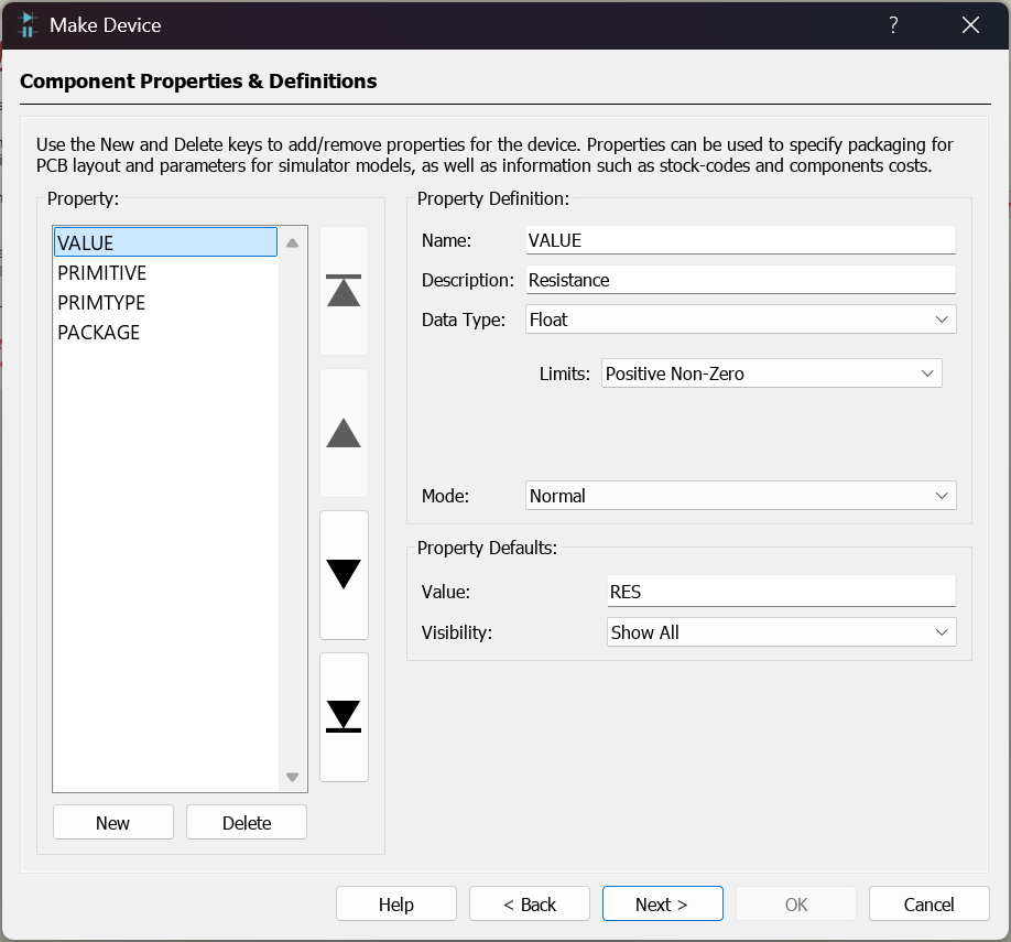
The Device Properties page of the Make Device dialogue form
If you add property definitions through Make Device then that definition and value is stored in the library for re-use in other projects. If you use the property editor in the Bill of Materials, the changes are applied only to the current schematic. You can of course then use the Compile To Library command on the Library menu to store the modified parts for future re-use.
See Also:
Properties (Bill of Materials)
What a Property Definition Contains
Each definition is edited through the same set of fields, some of which appear only for particular data types.
Name and Description
Name is the property keyword itself, such as PACKAGE or MODFILE. The combo offers the default definitions so that you can pick a familiar property rather than retype it. Description is the text used to label the field on the Edit Component dialogue form, so a VALUE property on a resistor can be labelled Resistance. Where no description is given, the property keyword is used as the label.
Data Type
The data type decides what control the user is given and what values are accepted.
| Data Type | Description |
| String | Free text. This is the default, and what a property gets if no definition applies. |
| Boolean (Checkbox) | A two-state property offered as Unchecked or Checked. Stored as 0 or 1. |
| Boolean (High/Low) | The same two states, offered as Low or High. |
| Boolean (Yes/No) | The same two states, offered as No or Yes. |
| Boolean (True/False) | The same two states, offered as FALSE or TRUE. |
| Keyword (Non-Editable) | A drop-down list of permitted values, taken from the Keywords field. The user must choose one of them. |
| Keyword (Editable) | The same list, but the user may type a value that is not on it. |
| Integer | A whole number, subject to the Limits setting. |
| Float | A floating point number, subject to the Limits setting. Engineering suffixes and property expressions are accepted. |
| Filename | A file, with a browse button. The Initial Directory, Ext'n and File Description fields configure the file selector that button opens. |
| Logic State | One of the seven digital simulator states, from strong low through floating to strong high. |
| PCB Package | A package name, with a Browse button onto the package libraries. The PCB Package(s) field holds the list offered in the drop-down. |
| Trace Mode | The diagnostic level for a simulator model, offered as Warnings Only, Trace Messages or Debug Messages. |
Mode
The mode decides how the property is presented to the user of the part, and whether they may change it.
| Mode | Description |
| Normal | The default. The property gets its own labelled field on the Edit Component dialogue form and the user can edit it. |
| Managed | The property is controlled by the librarian. On a managed part in a managed workflow its field is disabled, and the Manage Changes tool will overwrite the value when the part is updated. See Managed Properties below. Only the String, Boolean, Integer, Float and PCB Package data types may be made managed. |
| Logical | The property belongs to one element of a multi-element part rather than to the package as a whole, so each gate of a quad gate package can carry its own value. Proteus stores the per-element values with a letter suffix on the keyword, A for the first element, B for the second and so on, and presents the one belonging to the element you are editing under the plain keyword. Logical properties are dropped from the physical netlist, because they cannot be reduced to a single value for the part. |
| Read Only | The field is shown but is always disabled, whether or not managed libraries are in use. Use it for information that describes the part and should travel with it untouched. |
| Advanced | The property does not get a field of its own. Instead it is collected with the other advanced properties into an Advanced Properties selector at the foot of the form, where the user picks a property from the list and edits its value beneath. This keeps a long tail of rarely-changed simulator parameters from crowding the form. |
| Hidden | The property is not shown on the Edit Component dialogue form at all, and it is left out of the Bill of Materials and the Pick and Place output. The value is still carried by the part and still reaches the netlist. |
Limits
For the Integer and Float types, Limits constrains what the user may enter. The choices are None, Positive Non-Zero, Positive Or Zero, Negative Non-Zero, Negative Or Zero and Specific. Choosing Specific enables the Minimum and Maximum fields so that you can give an exact range. A value outside the permitted range is rejected when the user leaves the field, and the message names the property by its description, which is a further reason to fill the Description field in.
Keywords
For the two Keyword types, this field holds the list of values offered in the drop-down. Separate the keywords with a comma.
Property Defaults
The Property Defaults group sets the value a new component starts with, and how the property is displayed on the schematic. The visibility choices are Show All, Hide Keyword, Hide Value and Hide All, and they correspond exactly to the curly bracket syntax described in Object Properties.
Managed Properties
Managed properties are relevant only with the managed libraries workflow; if you do not have managed libraries then you can skip this section. In a managed workflow they serve two main purposes.
- Managed properties are read only to the user on the schematic.
- Managed properties will be overwritten by the Manage Changes tool during project review.
The former serves to protect the integrity of managed parts from accidental changes in the design and the latter is essential during part update and refresh by the reviewer.
In an unmanaged workflow, that is with the managed libraries checkbox in System Settings turned off, managed properties do nothing.
A managed property is one which the librarian wants to maintain control over, most likely as it helps describe the part or is relevant to the bill of materials. Examples include RoHS, MoQ, COST, SUPPLIER, CODE, and so on. By contrast an unmanaged property will be one that the user can change even in managed mode. Almost always these will be simulation properties not relevant to describing the physical ordering process.
A property is made managed by setting its Mode to Managed on this form, whether you reach the form through Make Device or through the System menu. You do not need the Library Manager to do it.
See Also:
Managed Properties (Library Manager)
Managed Libraries (Library Manager)
Default Property Definitions
A number of properties will be applied to most devices that you create. For example, anything that is going onto a PCB will need a PACKAGE property, and anything that has a simulator model will need a MODFILE, MODEL or SPICEMODEL property. You can also define a property definition for the part value. This allows you to change the description of the part value, and to provide range checking for it in the same way as for other properties.
You may also want to apply your own properties such as MoQ, SUPPLIER or COST to most of the devices that you create. If you plan to create managed libraries then you will want to make these managed properties as described above.
To make this easier, there is a list of default property definitions, which you can view, edit and delete with the Set Default Property Definitions command on the System menu. That command opens the Edit Default Property Definitions dialogue, which presents the same Component Properties & Definitions editor as the Make Device wizard. The properties defined here are offered on the Name field combo of the Device Properties page when you next make a device.
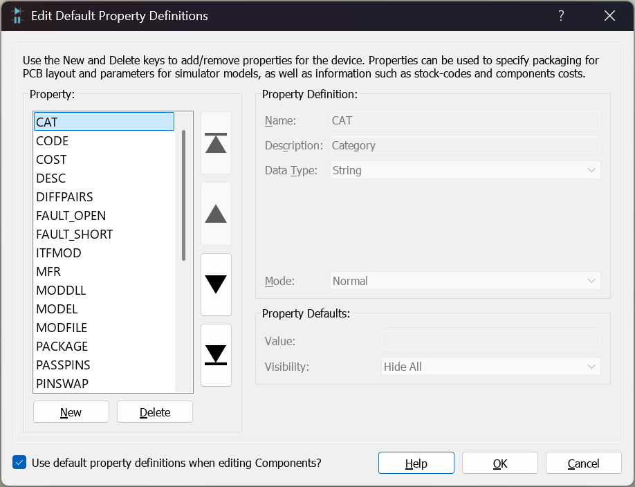
The Set Default Property Definitions dialogue, reached from the System menu
The dialogue also carries a checkbox, Use default property definitions when editing Components?. This is the switch that decides whether the default definitions are applied when a component is edited. With it clear, only definitions carried by the library part itself take effect, and a property covered solely by a default definition appears as plain text in the property block.
Alternatively, if you are not working with managed libraries, you can work directly through the Bill of Materials module. If you are working with managed libraries then all of these properties will be in your library parts and the way to change them is to update the managed library parts.
Where the Definitions are Stored
In either case, the information you define is held in a file called PROPDEFS.INI. The working copy of this file lives in the library directory given as your library path, and if you have configured more than one library directory then any one of them will serve.
Do not allow a PROPDEFS.INI to exist in more than one of your library directories. Proteus uses the first one it finds, so the others are silently ignored, and over time the copies will diverge until it is no longer clear which set of definitions is the live one. Keep a single file, in a single library directory.
Proteus also installs a reference copy of the file. At start-up it compares that copy against your working one and merges in any definitions that have been added by an update, so a new release can ship new default definitions without disturbing the ones you have written yourself.
Refer to the Library Manager help file to learn about managed libraries and working in a managed Proteus environment.