HOW TO MAKE SIMULATIONS RUN FASTER
Introduction
Although Proteus VSM is able to run many interactive simulations in real time, it should be fairly obvious that this cannot be the case for all circuits. For example, it is perfectly possible to draw a circuit that will oscillate at 1GHz, but there is no way that this can be simulated in real time on a computer that may not even execute one machine instruction in 1ns. In this section, we will explain in a little more detail what determines the complexity of a simulation and how you can optimise a circuit to maximise the simulation speed.
Using Digital Resistor and Diode Models
First and foremost in this context, it is vital to understand the difference between analogue and digital simulation within ProSPICE. This is because the simulation of digital circuitry is two or three orders of magnitude, that is up to 1000 times, faster than the simulation of analogue circuitry. It is for this reason that ProSPICE contains a digital simulator at all: by representing the operation of digital components as an event driven process, a great deal of unnecessary computation can be avoided.
Current hardware can simulate millions of digital events per second. The same machine will manage a sine wave generator running only up to a few kilohertz before the CPU load reaches 100%, because a 2kHz waveform requires about 60,000 analogue timepoints to be computed per second, and each timepoint requires a convergent solution of the circuit nodal equations to be established. That is a process vastly more complex than processing a simple digital event.
For many components, it should be fairly intuitive as to whether analogue or digital simulation will be required. For example, nearly all TTL and CMOS parts are represented by digital models, whereas analogue ICs such as op-amps, comparators and so forth are represented by analogue models. All components which are represented by standard SPICE models require analogue simulation.
However, a grey area arises for components which, though strictly analogue in nature, can be represented by a digital model for some purposes. In particular, diodes and, perhaps more surprisingly, resistors fall into this category. This becomes highly relevant in the context of wire-or logic, pull-up resistors, devices with open-collector outputs, and in diode-resistor logic networks.
Example 1: Wire-Or Logic
The following circuit section shows a typical wire-or logic network:
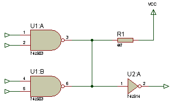
A wire-or network with two open-collector outputs and a pull-up resistor
U1:A and U1:B have open-collector outputs and can only sink current. A logic 1 output level results in a high impedance condition. In terms of DSIM, this means that the gate outputs drive either an SLO (strong low) or a FLT (floating) logic state. Now if resistor R1 is modelled in the analogue domain, PROSPICE must insert a digital to analogue interface object between the logic gates and the resistor, and then an analogue to digital interface object between the resistor and the input to U2:A. This will result in wonderfully detailed simulation of the rise-fall waveforms at this node, and the current flow through R1, but will also result in a great deal of computation every time the output of U1:A or U1:B changes state.
All this can be avoided if R1 is modelled digitally. In this case, its behaviour is to convert the SHI logic state of VCC to a WHI (weak high) logic level. When either NAND gate pulls low, the SLO state overrides the WHI state from the resistor and the net state is resolved to be logic low. But when neither gate sinks current, the WHI state beats the FLT state and the net rises to logic high. All this can be managed within the digital simulation paradigm and no analogue simulation is required.
Therefore, pull up resistors of any kind should almost always be modelled digitally.
Example 2: Diode-Resistor Logic
Another case where seemingly analogue circuitry can be modelled in the digital domain is diode-resistor networks of the sort shown below. These are often found around keypad scanning circuitry where the diodes serve to prevent short circuits between the row driving lines if more than one key is depressed simultaneously.
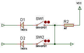
A diode-resistor logic network of the kind used in keypad scanning
As with the wire-or logic example, ProSPICE will quite happily model this in the analogue domain but it will be computationally expensive. If a digital resistor model is used as above, and a diode is seen as a device which will pass only a low logic level from cathode to anode and only a high logic level from anode to cathode, then the whole network can once again be modelled digitally.
Since keypad scanning routines tend to operate at some speed, and there are often numerous diodes and resistors, this is a very important optimisation to be aware of.
How to Select the Digital Resistor Model
- Point at the resistor you wish to change and press CTRL+E.
- Tick the Edit &all properties as text checkbox.
- Change the PRIMITIVE property to read
PRIMITIVE=DIGITAL,RESISTOR
If you are building a circuit from scratch, and know that you will want a particular resistor to be modelled digitally, you can also achieve this by picking the PULLUP or PULLDOWN models from the component library. These devices already contain the PRIMITIVE property as above.
How to Select the Digital Diode Model
- Point at the diode you wish to change and press CTRL+E.
- Tick the Edit &all properties as text checkbox.
- Change the PRIMITIVE
property to read
PRIMITIVE=DIGITAL,DIODE - Delete any MODEL property, as SPICE parameters have no meaning for the digital diode model.
If you are building a circuit from scratch, and know that you will want a particular diode to be modelled digitally, you can also achieve this by picking the DIODE-DIGITAL device from the component library. This device already contains the PRIMITIVE property as above.
Both forms of the property are accepted. Some library parts carry the type in a separate PRIMTYPE property instead, so that a part reads PRIMITIVE=DIGITAL on one line and PRIMTYPE=RESISTOR on another. Do not be surprised to find the assignment split in two when you open a shipped part.
Optimising Memory Accesses to External RAM and ROM
Many larger microprocessor designs make use of ROM, RAM or EEPROM memory devices external to the microcontroller itself. These may store the program code, or be used to supplement internal SRAM present within the CPU chip itself. Given a correct address decoding circuit, and assuming that the memory device is modelled, Proteus VSM will correctly simulate such designs as drawn. When the CPU accesses external memory, the model will drive the address, data and control lines appropriately, and external decode logic and memory model will respond by reading or writing the appropriate locations.
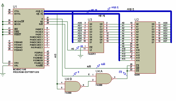
A microcontroller design with external RAM and ROM on a shared address and data bus
This is quite useful if you wish to verify that your memory decoding circuitry works as designed, but is also extremely expensive in terms of computation. Setting up a 16 bit address will create a minimum of 16 digital events and reading or writing a byte of data to or from the data bus will generate another 8. Removing the data from the bus afterwards will create another 8 events. Where address and data lines are multiplexed, as in the design above, even more events will be generated. All this compares very unfavourably with the ability of a VSM CPU model to execute an instruction using just one event per machine cycle.
Therefore, we have provided the CPU models with the ability to simulate accesses to external memory internally to the model. This applies to the larger AVR models and to the ARM7/LPC2000 models; only the ARM7 models support EXTROM as well as EXTRAM. External memory may be declared using EXTRAM or EXTROM properties which specify the memory range for each block of external memory. Full details are provided in the model specific help for these processors, which you can access from the Edit Component dialogue form.
Once the external memory map has been defined in this way, instructions which access external memory within the specified ranges can be simulated without generating large numbers of digital events. Accesses to memory mapped peripherals can still be fully simulated, since these will lie at locations outside the memory ranges specified in the EXTRAM and EXTROM properties.
See Also: