HINTS AND TIPS
Circuit Timescale
Interactive simulations will be generally be viewed in real time, so it is no use drawing circuits with 1MHz clocks, or 10kHz sine wave inputs unless you also adjust the Timestep per Frame value in the Animated Circuits Configuration dialogue.
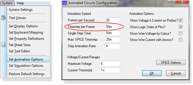
Change the Time Step per Frame
If you do attempt to simulate something that operates very quickly, there are several things to bear in mind:
- Given finite CPU power, only a certain amount of simulation time can be computed in a fixed amount of real time. PROTEUS VSM is designed to maintain its animation frame rate (frames per second) whatever, and to cut short any frames which are not completed in the available time. The consequence of this is that very fast circuits will simulate slowly (relative to real time) but smoothly.
- Analogue component models simulate very much more slowly than digital ones. On current hardware you can simulate digital circuitry operating at around 20MHz in real time, whereas the practical ceiling for analogue circuitry is orders of magnitude lower.
Consequently it is very silly to attempt to simulate clock oscillators for digital circuitry in the analogue domain. Instead, use a Digital Clock generator and set its Isolate Before checkbox so that the analogue clock is not simulated.
Voltage Scaling
If you intend to use coloured wires to indicate node voltages you need to give some thought as to the range of voltages that will occur in your circuit. The default range for displayed voltages is +/-6V so if the circuit operates at significantly different voltages from this you may need to change the Maximum Voltage value in the Animated Circuits Configuration dialogue.
Earthing
PROSPICE will attempt to define a sensible earth point for any active circuit which does not specifically include a ground terminal. In practice this is usually chosen as the mid-point of the battery, or the centre tap if the circuit has a split supply. It follows that the positive terminal of the battery will sit above ground and the negative terminal below it, corresponding to red and blue wire colours. However, if this behaviour is not what is required, you always have the option of explicitly defining the ground reference point using a ground terminal on the schematic.
Advanced users can influence the automatic earthing through the GEARTH property on a component, which defaults to 1E-8. Setting GEARTH to zero on a component turns the automatic fix off, and the simulator then reports "Net ... has no DC path to ground." as a warning for each net it would otherwise have fixed. Every fix that is applied is written to the simulation log on the DC Paths trace channel, which you enable from the Configure Diagnostics dialogue, so you can see exactly what the automatic earthing has done to your circuit.
High Impedance Points
The automatic earthing logic also checks for any device terminals which are not connected to ground, and will insert high value resistors automatically in order to ensure convergence of the SPICE simulation. With the default settings the resistor value is 100M ohms, shared between the pins on the net that asked for it. This means that ill formed circuits, for example circuits with unconnected or partially connected components, will generally simulate, although there can sometimes be strange results.