TAKING MEASUREMENTS
Overview
There are several different ways of taking measurements during an interactive simulation. These include
- Animation effects.
- Point and shoot operating parameter information.
- Voltage and current probes.
- The System Scope and the System Meter.
- Virtual instruments.
Animation Effects
As well as any active components in the circuit, a number of other animation effects may be enabled to help you study the circuit operation. These options may be enabled using the Set Animation Options command on the System menu, which opens the Animated Circuits Configuration dialogue. The settings are saved with the design.
Two of the four effects are on by default, Show Logic State of Pins? and Show Voltage & Current on Probes?. The two wire effects, Show Wire Voltage by Colour? and Show Wire Current with Arrows?, are off by default because of the extra work they ask of the simulator.
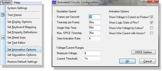
Configuring Animation Options in Proteus
Show Voltage & Current on Probes?
This option gives each voltage or current probe on the schematic a live readout of the value it is measuring, updated as the simulation runs. It is what makes the probes described below useful during interactive simulation, and it is enabled by default.
Show Logic State of Pins?
This option displays a coloured square by each pin that is connected to a digital or mixed net. By default, the square is blue for logic 0, red for logic 1 and grey for the undefined state, which the dialogue calls Logic '?'. The colours may be changed via the Set Design Defaults command on the Template menu as shown below:
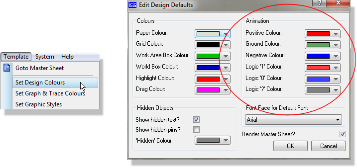
Configuring Logic State Colours in Proteus
Enabling this option incurs a modest extra burden on the simulator, but can be very, very useful when used in condition with breakpoints and single stepping as it enables you to study the state of a microcontrollers output port pins as the code is single stepped.
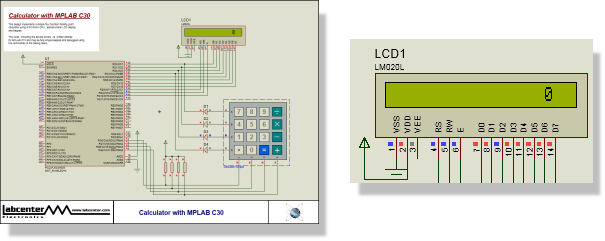
Logic States on Pins in Proteus
Show Wire Voltage by Colour?
This option causes any wire that is part of an analogue or mixed net to be displayed in a colour that represents its voltage. By default, the spectrum ranges from blue at -6V through green at 0V to red at +6V. The voltages may be changed on the Animated Circuits Configuration dialogue, and the colours via the Set Design Defaults command on the Template menu.
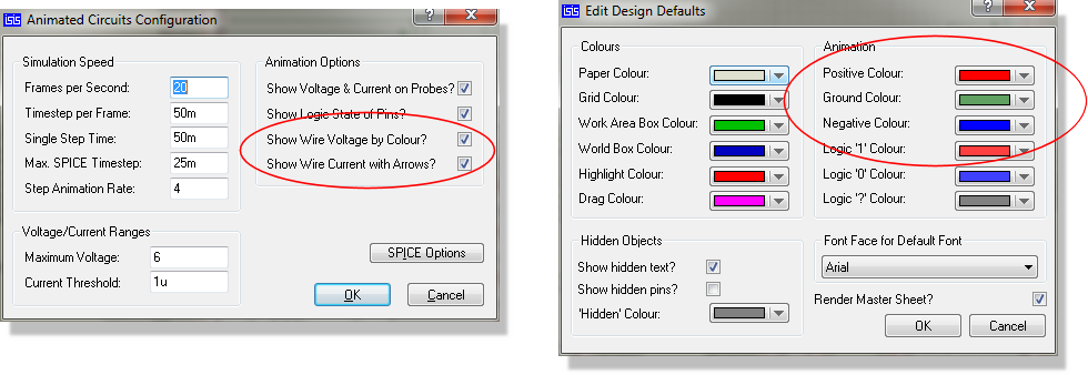
Configuring Wire Voltage thresholds and colours in Proteus.
This option is off by default. Enabling it incurs a modest extra burden on the simulator but is very effective for helping novices understand a circuits operation, especially when used in conjunction with the Show Wire Current with Arrows? option.
Show Wire Current with Arrows?
This option causes an arrow to be drawn on any wire that is carrying current. The direction of the arrow reflects conventional current flow, and it is displayed if the magnitude of the current exceeds a threshold. The default threshold is 1uA, although this can be changed on the Animated Circuits Configuration dialogue.
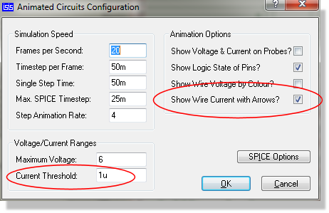
Setting the current threshold at which wire arrows are drawn
Computing the wire currents involves the insertion of a zero value voltage source in every wire segment in the schematic (apart from inside models) and this can create a large number of extra nodes. Consequently the burden on the simulator can be significant, and the option is off by default. However, the arrows are most useful in teaching basic electricity and electronics where the circuits tend to be fairly simple. They also govern whether the System Meter can read wire currents.
See Also:
Set Animation Options, for the individual fields of the Animated Circuits Configuration dialogue.
Point and Shoot Parameter Information
You can interrogate any of the components in the schematic to obtain information about their current status whenever the simulation is paused. At the least this will be a summary of their node voltages and/or pin logic states but some components will display additional data such as relative (pin-pin) voltages and power dissipation.
To display parameter values:
- Ensure that the simulation is paused using the
Animation Control Panel.

- Click left on any component to view its parameters.
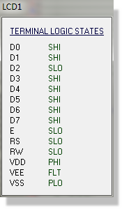
DC Operating Point
If you view parameter information at time zero, then you are viewing the DC operating point of the circuit. Otherwise, the parameters displayed represent instantaneous values as at the time you paused the simulation. This is particularly significant for power dissipation values; these numbers are not averaged in any way whatsoever and represent a simple multiplication of instantaneous voltage multiplied by instantaneous current.
Analogue or Digital?
Where a component pin is on a net which carries only digital logic states (i.e. there are no analogue components connected to it), Proteus VSM will display the terminal voltage as a logic state. Otherwise an analogue node voltage is displayed.
Voltage and Current Probes
The voltage and current probe objects are most commonly used in graph based simulations, where the voltages and currents being measured can be plotted out on a graph. Graph based simulation requires the Advanced Simulation Features module, but the probes themselves do not: you can also use them during interactive simulation to display node voltages or currents which update in real time. The readout beside the probe appears only while Show Voltage & Current on Probes? is enabled, which it is by default.
The probe objects have three advantages over the virtual ammeters and voltmeters:
- They can be added and removed to any point in the circuit without drawing wires.
- They take up much less room on the schematic.
- They can be used to trigger a Real Time Breakpoint, which halts the simulation when the measured value reaches a trigger value you set.
Voltage probes dropped onto nets which carry only digital signals (i.e. to which no analogue components are connected) will display logic states rather than node voltages.
To place voltage or current probes
- Select the Voltage Probe or Current Probe as appropriate.
- Click left on the wire that you wish to measure to add the probe.
Note that current probes are directional, and measure conventional current as indicated by their arrow symbol. The arrow must be parallel to the wire segment on which the probe is placed.
Two further probe settings matter during interactive simulation. A voltage probe can apply a resistive load between the point it is measuring and ground, which is how you give a measured point a DC path to ground where it would otherwise have none. Either type of probe can also record the waveform it captures to a file, which can then be played back into another circuit with a tape generator.
See Also:
Edit Voltage Probe, for the individual fields of the probe dialogue.
The System Scope and System Meter
Two instruments are available during any interactive simulation without your having to change the schematic at all. Both are launched from the Animation Control Panel.
The Scope button opens the System Scope, an oscilloscope whose probes are attached to the signals of interest live, and can be moved to other signals as the simulation progresses.
The Multimeter button opens the System Meter, a virtual multimeter with two live probes, A and B. It reads the voltage at either probe, the difference between them, or the current in a probed wire, on either AC or DC coupling, and it will capture the minimum and maximum values it sees. Current reading depends on the Show Wire Current with Arrows? option described above, because that is what puts the measuring elements into the netlist.
Both windows open docked at the bottom of the application window, where they share a tab strip with each other. You can float them or move them as you prefer, and the arrangement you leave them in is restored the next time you simulate.
See Also:
Virtual Instruments
A wider selection of instruments can be placed on the schematic and wired into the circuit. Click the Virtual Instruments Mode button on the mode toolbar and the Object Selector will list the instrument types available. Select the one you want and place it on the schematic just as you would an ordinary component, then wire it to the signals you want it to measure.
The instruments supplied are:
- Oscilloscope
- Logic Analyser
- Signal Generator
- Pattern Generator
- System Meter
- SPI Debugger
- I2C Debugger
- Virtual Terminal
- Voltmeters and Ammeters
- Timer/Counter
- CAN Bus Analyser
See Also:
Virtual Instruments, for how to use each instrument.