PROBES
Overview
A probe is an object that can be set up to record the state of the net to which it is connected. Three types of probe are placed from the Probes selector:
- Voltage probes, which can be used in both analogue and digital simulations. In the former they record true voltage levels, whilst in the latter they record logic levels and their strengths. A voltage probe can also be placed on a bus.
- Current probes, which can only be used in analogue simulations, and must be placed on a wire such that the wire passes through the probe. The direction of measurement is indicated by the current probe graphic.
- Tapes, which record a net to a file during one simulation so that it can be played back into another. A tape is placed in the same way as a probe and is documented in Tapes and Partitioning.
You cannot use current probes in digital simulations, or on buses. A current probe placed on a bus is reported in the simulation log as "Current probe on bus not supported".
Probes are most normally used in Graph Based Simulations, but can also be used in interactive simulations to display operating point data and to partition the circuit.
The System Scope and the System Meter use live probes of their own, which are attached to a net while the simulation runs rather than placed on the schematic beforehand. See System Meter in the Instruments manual.
Placing Probes
To Place a Probe:
- Select the Voltage Probe or Current Probe icon. A preview of the probe appears in the Overview Window.
- Use the Rotation and Mirror icons to orient the probe according to how you want to place it.
Note that, for a current probe, correct orientation is important. Current flow is measured in the direction indicated by the arrow enclosed in a circle which forms part of the probe's symbol. - Place the mouse in the Editing Window and click left to attach the probe to the mouse. Move the probe to the correct position and click left again to drop it on to the wire.
You can place a probe directly on to an existing wire by placing it such that its connection point touches the wire. Alternatively you can place several probes in a free area of your design, and wire to them later.
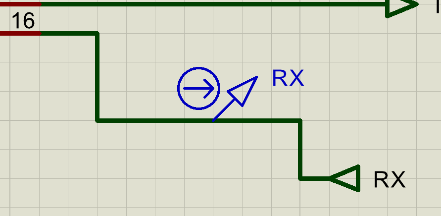
The current probe symbol, with the arrow in the circle showing the direction in which current is measured
Probes take their names automatically from the net they are connected to, by exactly the same rules as generators. An unconnected probe is named with a question mark, a probe on a named net takes the net name, and a probe on an unannotated net takes the reference and pin name of the nearest pin on the net, in the form U1(OUT). Typing a name of your own fixes it; clearing the name back to blank restores automatic naming.
See Also:
Placing Generators, for the full statement of the naming rules.
Probe Settings
To open a probe for editing, either point at it and press CTRL+E, or right click it and choose Edit Properties from the context menu.
There are two forms, according to the probe. A voltage probe opens the Edit Voltage Probe form, which carries four groups of settings and is described below. A current probe opens the smaller Edit Current Probe form, which carries only the probe name and the waveform recording controls: a current probe has no load resistance, no breakpoint and no isolate setting.
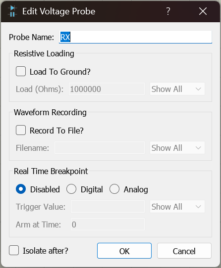
The Edit Voltage Probe dialogue form
Probe Name
The name the probe carries on the schematic and, more usefully, the name it is known by when you add it as a trace to a graph. Typing a name here fixes it, so that it no longer changes when the probe is moved to another net. Clear the field to blank and click OK to hand the probe back to automatic naming.
Resistive Loading
Voltage probes may be set to impose a load resistance on the schematic. This is useful where there would otherwise be no DC path to ground from the point being measured, which the simulator cannot solve.
Check Load To Ground? to apply the load and enter its value in the Load (Ohms): field, which writes the LOAD property. The default is one megohm.
Waveform Recording
Both current and voltage probes can record data to a file, which can then be played back by a tape object set to PLAY mode. This lets you create test waveforms using one circuit and then play them back into another.
Check Record To File? and enter a name in the Filename: field, which writes the RECORD property. If you give a bare filename with no path, the file is written to the RESULTS folder rather than alongside the project. Proteus creates that folder the first time it is needed, asking you to confirm before it does so.
Recording works in graph based simulation only. A probe set to record in an interactive simulation is reported in the simulation log as "RECORD mode of probe not supported in interactive simulation."
Real Time Breakpoint
A voltage probe can halt the interactive simulation the instant the net it is watching reaches a value you specify. This is the circuit equivalent of a code breakpoint, and it is one of the fastest ways there is to catch a fault: put a probe on the net that misbehaves, tell it what value counts as misbehaviour, and the simulation stops at the moment it happens with every other node, register and variable in the design frozen for you to inspect.
The breakpoint is switched on and its domain chosen with the three buttons at the top of the group.
- Disabled, the default, means no breakpoint. The trigger fields are greyed out.
- Digital treats the net as a logic signal, so the Trigger Value: is 0 for logic low and 1 for logic high. The setting is held in the RTDBREAK property.
- Analog treats the net as an analogue signal, so the Trigger Value: is the voltage you want to stop at. The setting is held in the RTVBREAK property.
The Arm at Time: field holds the breakpoint inactive until the given simulation time. Use it to stop a breakpoint firing on start-up transients or while initialisation logic runs, which is otherwise the commonest reason for a breakpoint to trigger on something you did not mean.
Typical uses are catching a supply rail that sags under load, catching an output that goes high when it should stay low, and stopping the moment a signal crosses a threshold so that you can read the surrounding circuit at that instant.
Isolate After
Check Isolate after? and a voltage probe placed in the middle of a wire breaks the wire, isolating the circuitry the probe connects to from the circuitry after it. Together with the generator's Isolate Before? setting this is how a design is split into pieces that can be simulated separately, with tapes carrying the signals between them.
Visibility
Each of the three groups carries its own selector governing how that group's setting is drawn beside the probe on the schematic. Show All draws the property name and its value, Hide Name draws the value alone, Hide Value draws the name alone, and Hide All draws neither, so the setting is in force but nothing appears on the drawing.
See Also:
Edit Voltage Probe, for the dialogue form field by field.
Tapes and Partitioning, for recording, playback and splitting a design into partitions.
Breakpoint Triggers, for the dedicated breakpoint trigger objects.