Creating, Editing & Debugging EasyHDL Scripts
EasyHDL scripts can be local to a particular generator object, they can be placed on the schematic and then associated with multiple generators in order to specify a complex set of test vectors, or, where the design contains a microcontroller with a VSM Studio firmware project, they can be authored as .ehdl source files held within that project.
To create a local EasyHDL script for a single generator:
- Select the Generator icon to place a generator or else click right and then left to edit an existing one.
- Set the generator type to Easy HDL. This can be analogue or digital according to the type of generator that you want to create.
- Type the script into the Local Script editor field. This field is a full EasyHDL editor and colours keywords, comments and strings as you type, so you can write the script directly on the dialogue form.
The output pin is automatically assigned the name 'OUT'. If you specified an analogue generator in step 2, then OUT will be a NODE variable; if you specified a digital generator then OUT will be a PIN variable.
To create an EasyHDL script on the schematic:
- Select the Script icon and click left to place
a script object. The Edit Script dialogue form will appear.
 Scripts
in the Schematic Capture manual gives general instructions on placing and editing
text scripts.
- The first line of the script must be:
*SCRIPT GENERATOR script_name
The keyword SCRIPT indicates that the text in the script block is to be included in the netlist, whilst the keyword GENERATOR indicates to PROSPICE the type of script (for the purpose of linking it). The name after GENERATOR keyword is a name supplied by you to identify the script. Any sequence of alphanumeric characters and the underscore character ('_') may be used; a space or any other character will be seen as the end of the script name. - The last line in the script must be:
*ENDSCRIPT
This indicates the end of the script to the netlist loader in PROSPICE; ISIS will report it as missing if it is not found during netlist compilation. Anything after this line will not be included in the netlist, and is effectively ignored. - Enter your EasyHDL script between the opening *SCRIPT... and closing *ENDSCRIPT. You will need to declare the generators as NODE or PIN variables.
- Close the edit script dialog form when you are done.
To create an EasyHDL script in a VSM Studio project:
If your design contains a microcontroller, its VSM Studio firmware project can also host EasyHDL scripts as ordinary source files. A script authored this way is contributed to the netlist as a named script when the simulation starts, so it behaves exactly like a script placed on the schematic and can drive one or many generators.
- Open the design's firmware project in VSM Studio. Right click on the Generator Scripts category in the project tree and select Add New File (or Add Files to bring in a file that already exists). Give the file the .ehdl extension.
- The base name of the file is the script name. A file named TEST.ehdl, for example, provides a named script called TEST.
- Enter your EasyHDL script directly into the file. Unlike a script object on the schematic, you do not write the *SCRIPT ... *ENDSCRIPT wrapper. VSM Studio registers the text under the script name for you, so the file holds the script body only.
- As with any named script there is no implicit OUT pin. Declare each net you wish to drive as a PIN (digital) or NODE (analogue) variable whose name matches the generator, then assign to it. For example, to drive a digital net called S0:
PIN S0
S0 = TRUE
If a generator's name is not a valid EasyHDL variable name, for instance because it contains spaces or brackets, give it a legal handle with the ALIAS command first, then declare and drive that handle:
ALIAS SIG=Test Signal
PIN SIG
SIG = TRUE
Finally, tell each generator to use the script. Edit the generator, set its type to Easy HDL, tick Manual Edits? and add a SCRIPT property set to the file's base name, for example SCRIPT=TEST.
A script held in a project does not appear in the generator's Assigned Script selector (which lists only <LOCAL> and scripts placed on the schematic), so it must be assigned through the SCRIPT property as above. The binding is resolved when the simulation starts.
Because the project script is not in the selector, check the generator's SCRIPT property after any later visit to the generator dialogue, and set it again if it has been lost.
The file is given EasyHDL syntax highlighting and is excluded from the firmware compile, so it will not affect the microcontroller program. A single .ehdl file may drive several generators, which is convenient when the same set of test vectors is shared between them.
Three further points are worth knowing about scripts held in a project:
- The script text is taken from the editor rather than from disk, so edits you have made but not yet saved are picked up when the simulation starts. There is no need to save the file first.
- If two projects in the design contribute files with the same base name, a warning is written to the simulation log and only the first of them is used. Give each generator script a distinct name.
- The Generator Scripts category itself cannot be renamed.
Because a script authored this way is an ordinary project file rather than a schematic object, it can also be written and edited by ProPilot and ProTutor. The assistants reach the .ehdl file through the same interface they use for firmware sources, so they can generate and refine your test vectors alongside the code they are written to exercise.
To link generator objects to a schematic based script:
- Select the Generator icon to place a generator or else click right and then left to edit an existing one.
- Set the generator type to Easy HDL. This can be analogue or digital according to the type of generator that you want to create.
- Use the Assigned
Script selector to specify the script that will drive the generator.
The generator name must match a NODE
or PIN
variable declared in the assigned script: in other words, give the generator the same name as the variable you want it to follow.
The names offered by the Assigned Script selector are script names, not generator names. The selector lists only <LOCAL> and script objects placed on the schematic; a script that lives in a VSM Studio project does not appear in it. To drive a generator from a project script, tick Manual Edits? on the generator dialogue and set the generator's SCRIPT property to the file's base name, for example SCRIPT=TEST. The binding is resolved when the simulation starts. The same name may be given to several generators so that they share one set of test vectors.
Debugging EasyHDL Scripts
To debug a generator script during simulation:
- Place the generator in the normal way, set the generator type to be Easy HDL and write the script.
- Tick Debug this generator? on the dialogue form underneath the script. This sets the generator's DEBUG property, which is what the simulator looks for when it decides which scripts to make debuggable.
- Pause the simulation to see the source and variables for the script.
- Set breakpoint(s) in the source window (double click on the source line in question) and then run the simulation.
- When the breakpoint is hit the simulation will pause and you can single step the script, monitoring variable changes in the normal way.
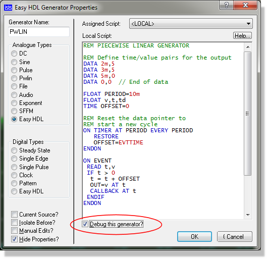
Specifying an EasyHDL piecewise linear script as being active for debugging
From a user interface perspective, debugging an EasyHDL script is largely identical to debugging microcontroller firmware in Proteus VSM, and the Source Level Debugging topic covers the basic operation. Beyond that however, there are a few subtle differences that you should bear in mind:
- EasyHDL statements execute in zero time. It follows that when you single step EasyHDL code, the electrical simulation does not advance after each step. This is significantly different from stepping microcontroller code, in which each instruction takes a finite time to execute and the simulation advances in time as you step the code.
- Since time does not advance after each statement, the effect of any output assignments made in the script will not be seen in the circuit until either the end of the script is reached, or, in the case of a digital script, a SLEEP or WAIT statement is reached.
- All scripts are executed once at the start of the simulation. Therefore, any breakpoints that can be reached from the start of the script will trigger before the circuit operating point has been computed. This may result in unusual voltage and logic state values being displayed on the schematic. In this situation, the operating point will be re-computed after each step until the end of the script has been reached.
- Breakpoints and single stepping are not enabled when an analogue script is invoked on an ordinary analogue time point. Debugging is only active when the script is invoked by a timer or other callback event.
Suspending the Simulation from the Script
A script can also suspend the simulation itself, which is often more convenient than hunting for the right line to breakpoint on. The PAUSE command halts the simulation at the point it is executed and writes a message of the form EASYHDL script paused at line 12 to the simulation log, so you can see which statement stopped it. Because it is an ordinary command it can be placed inside a conditional, which makes it a direct way to stop on a data-dependent condition:
IF v > VMAX THEN PAUSE
Execution resumes at the following statement when you restart the simulation. PAUSE is ignored during settle passes and during ordinary analogue timepoints, for the same reason that breakpoints are not offered there.
Several examples of EasyHDL scripts can be found in the Generator Scripts subdirectory of the Samples directory supplied with your Proteus installation. These range in complexity from a simple sine wave through to a complete QPSK Modulator and are well worth exploring.
See Also: