GENERATORS
Overview
A generator is an object that can be set up to produce a signal at the point at which it is connected. There are many types of generator, each of which generates a different sort of signal:
| Generator | Description |
DC |
Constant DC voltage or current level. |
Sine |
Sine wave generator with amplitude, frequency and phase control. |
Pulse |
Analogue pulse generator with amplitude, period and rise/fall time control. |
Exp |
Exponential pulse generator, producing pulses with the same shape as RC charge and discharge circuits. |
SFFM |
Single Frequency FM generator, producing waveforms formed by the frequency modulation of one sine wave by another. |
Pwlin |
Piece-wise linear generator for arbitrarily shaped pulses and signals. |
File |
As above, but the data is taken from an ASCII file. |
Audio |
Uses Windows WAV files as the input waveform. These are especially interesting when combined with Audio graphs as you can listen to the effect of your circuit on audio signals. |
Random |
Pseudo-random noise source with a settable amplitude and sample frequency, an optional low pass filter that shifts the noise from white towards pink, and a choice between a repeatable seed and a fresh seed on every run. |
DState |
Steady state logic level. |
DEdge |
Single logic level transition or edge. |
DPulse |
Single digital clock pulse. |
DClock |
Digital clock signal. |
DPattern |
An arbitrary sequence of logic levels. |
Scriptable |
Analogue or digital waveform defined by an EasyHDL script. |
Placing Generators
To Place a Generator:
- Obtain a list of generator types by selecting the Generator Mode icon. The list of generator types is then displayed in the Object Selector.
- Select the type of generator you wish to place from the selector. A preview of the generator appears in the Overview Window.
- Use the Rotation and Mirror icons to orient the generator according to how you want to place it.
- Place the mouse in the Editing Window and click left to attach the generator to the mouse. Move the generator to the correct position and click left again to drop it.
You can place a generator directly on to an existing wire by placing it such that its connection point touches the wire. Alternatively you can place several generators in a free area of your design, and wire to them later.
Automatic Naming
When a generator is placed unconnected to any existing wires it is given a default name of a question mark (?) to indicate that it is unannotated. When the generator is connected to a net, which can happen as you place it if you drop it directly on to an existing wire, it takes the name of the net. If the net itself is unannotated the generator takes the reference and pin name of the nearest pin on the net, written in the form U1(OUT). This is the name you will see against the trace on a graph and in the simulation log, so it is worth recognising.
Where the net carries a label, the label always takes precedence over a pin name, and where there is more than one candidate the one nearest the generator is used. The name is updated automatically as the generator is unwired or as it is dragged from one net to another.
You can assign your own name to the generator by editing it, in which case the name becomes permanent and is no longer updated. Clearing the name back to blank restores automatic naming.
The same placement and naming rules apply to probes and to tape objects. See Placing Probes.
See Also:
Net Names, for an explanation of nets and net naming.
Editing Generators
To open a generator for editing, either point at it and press CTRL+E, or right click it and choose Edit Properties from the context menu. Both routes open the Edit Generator dialogue form.
The form provides a number of common fields together with a further set of fields that change according to the generator's type. The common fields are described in the next section, and the fields specific to each type are described in that type's own section below.
Common Dialogue Fields
Generator Name
The name the generator carries on the schematic. Typing a name here locks it, so that it survives being moved to another net. Clearing the field to blank restores automatic naming, as described under Placing Generators above.
Analogue Types and Digital Types
Two groups of radio buttons select what the generator is. The Analogue Types group offers DC, Sine, Pulse, Pwlin, File, Audio, Exponent, SFFM, Random and Easy HDL. The Digital Types group offers Steady State, Single Edge, Single Pulse, Clock, Pattern and Easy HDL. Changing the selection converts the generator and swaps the pane of type-specific fields underneath.
Current Source?
Check this box to make the generator inject a current rather than drive a voltage. The type-specific fields relabel themselves accordingly, so that a DC generator's Voltage (Volts): field becomes Current (Amps): and a Pulse generator's Initial (Low) Voltage: field becomes Initial (Low) Current:, and the simulator netlists a current source in place of a voltage source.
The option is available for the DC, Sine, Pulse, Pwlin, Exponent and SFFM generators and for the analogue Easy HDL generator. It is greyed out for the File, Audio and Random generators and for every digital type, all of which are voltage sources only.
Isolate Before?
A generator placed in the middle of a wire normally drives the whole net. Check this box and it breaks the wire instead, driving only the circuitry in front of it and leaving the stage that would otherwise feed that point disconnected. This is how you inject a stimulus part way into a design without having to delete the circuitry that precedes it. The probe side of the same idiom is Isolate after?, described in Isolate After.
Hide Properties?
Controls whether the generator's properties are drawn next to it on the schematic. New generators are created with their properties hidden.
Manual Edits?
Replaces the pane of type-specific fields with the Edit Generator Properties editor, in which the properties are typed directly, one NAME=VALUE pair to a line. This is the quickest route when you have tabular data to enter, and it is the only route to a property the typed form does not offer. Only property names that are valid for the selected generator type are accepted, so a mistyped key is reported rather than silently stored.
Proteus switches to manual editing on its own if it opens a generator whose property set cannot be represented on the typed form. If the dialogue opens in the property editor when you were expecting the usual fields, that is why.
See Also:
Edit Generator, for the dialogue form field by field.
DC Generators
The DC generator is used to generate a constant analogue DC voltage or current level. The generator has a single property, VALUE, which is set from the form's Voltage (Volts): field, or Current (Amps): when Current Source? is checked. A new DC generator is created with a value of zero.
Sine Generators
The Sine generator is used to produce continuous sinusoidal waves at a fixed frequency. A number of parameters can be adjusted:
- The output level is specified as a peak amplitude (VA) with optional DC offset (VO). The amplitude may also be specified in terms of RMS or peak to peak values, using the Peak-Peak: and RMS: fields on the form. These write the properties PEAK and RMS; the simulator halves a PEAK value and multiplies an RMS value by the square root of two to arrive at the peak amplitude it actually uses.
- The frequency of oscillation can be given in Hz (FREQ), or as a period (PER), or as a number of cycles over the whole graph, using the Cycles/Graph: field. If you give neither a frequency nor a period, the period is taken as the length of the graph, which is one cycle.
- A phase shift can be specified in either degrees (PHASE) or as a time delay (TD). In the latter case, oscillation does not start until the specified time. Note that a negative phase is converted into a time delay, so that a phase of -90 degrees on a 1kHz sine wave delays the waveform by 250us.
- Exponential decay of the waveform after the start of oscillations is specified by the damping factor, THETA.
| Symbol | Description | Default (new generator) | If the property is deleted |
VO |
The DC offset. Also accepted as OFFSET. |
0 |
0 |
VA |
The peak amplitude. Also accepted as AMP. |
1 |
1 |
PEAK |
Peak to peak amplitude, used in place of VA. Halved by the simulator. |
Not set |
Not used |
RMS |
RMS amplitude, used in place of VA. Multiplied by the square root of two. |
Not set |
Not used |
FREQ |
The frequency in Hz. |
1 |
One cycle over the whole graph |
PER |
The period in seconds, used in place of FREQ. |
Not set |
Not used |
PHASE |
The phase in degrees. A negative value is converted into a time delay. |
0 |
0 |
TD |
The time delay in seconds, used in place of PHASE. Also accepted as DELAY. |
Not set |
0 |
THETA |
The damping factor in 1/s. Zero gives an undamped wave. |
0 |
0 |
Mathematically, the output is given by:
V=VO+VAe-(t-TD)THETA sin(2pFREQ(t-TD))
for t >= TD. For t < TD the output is simply the offset voltage, VO.
Pulse Generators
The Pulse generator is used to produce a variety of repetitive input signals for analogue analyses. Square, saw-tooth and triangular waveforms can be produced, as well as single short pulses. The operation of the pulse generator is best described by the following diagram:
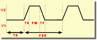
The pulse generator parameters
where
| Symbol | Description | Default (new generator) | If the property is deleted |
V1 |
The low level value of the output. Also accepted as LOW, which is the name the dialogue writes. |
0 |
0 |
V2 |
The high level value of the output. Also accepted as HIGH. |
1 |
1 |
PER |
The period of the waveform. If none is specified, FREQ is used instead. |
Not set |
Not used |
FREQ |
The frequency of the waveform. The form also offers a Cycles/Graph: field, which sets the frequency as a number of cycles over the whole graph. |
1 |
One cycle over the whole graph |
PW |
The time for which the output is at V2 in each cycle, excluding TR and TF. The Pulse Width: field can be given in seconds or as a percentage of the period, and a percentage is what a new generator carries. |
50% |
Half the period |
TR |
The rise time, that is the time taken between the low and high levels in each cycle. |
1us |
One thousandth of the pulse width, with a floor of 1ps |
TF |
The fall time, that is the time taken between the high and low levels in each cycle. The simulator applies the same rule to it as to TR, so unless you set it explicitly it matches the rise time. |
1us |
One thousandth of the pulse width, with a floor of 1ps |
TD |
The delay time. The output of the generator starts at V1 and remains at that level for TD seconds. The field is labelled Start (Secs):. |
0 |
0 |
A truly square wave is not available, because instantaneous changes are not allowed in PROSPICE. Setting the rise or fall time to zero is not rejected; the simulator quietly substitutes a single simulation timestep, so the edge becomes as steep as the analysis allows rather than vertical.
Exponential Generators
The Exp generator produces the waveforms of an RC circuit under charging and discharging conditions. The parameters are best described by the diagram below:
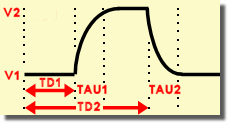
The exponential generator parameters
where the parameters are:
| Symbol | Description | Default (new generator) | If the property is deleted |
V1 |
The initial level, set from the Initial (Low) Voltage: field. Also accepted as LOW, which is the name the dialogue writes. |
0 |
0 |
V2 |
The pulsed level, set from the Pulsed (High) Voltage: field. Also accepted as HIGH. |
1 |
1 |
TD1 |
The rise start time in seconds, set from the Rise start time (Secs): field. |
0 |
0 |
TAU1 |
The rise time constant in seconds, set from the Rise time constant (Secs): field. |
1 |
One tenth of the simulation stop time |
TD2 |
The fall start time in seconds, set from the Fall start time (Secs): field. |
1 |
TD1 plus half the simulation stop time |
TAU2 |
The fall time constant in seconds, set from the Fall time constant (Secs): field. |
1 |
The same as TAU1 |
Mathematically, the waveform is defined in three sections:
0 to TD1 |
V1 |
TD1 to TD2 |
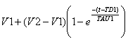 |
TD2 to TSTOP |
 |
Single Frequency FM Generators
The SFFM generator produces a waveform that represents the result of frequency modulating one sine wave with another. Mathematically, this is represented as:
V = VO + VAsin (2pFCt + MDI sin(2pFSt))
where the parameters are:
| Symbol | Description | Default (new generator) | If the property is deleted |
VO |
The DC offset voltage. Also accepted as OFFSET, which is the name the dialogue writes. |
0 |
0 |
VA |
The carrier amplitude. Also accepted as AMP, and as PEAK or RMS with the same conversions as the Sine generator. |
1 |
1 |
FC |
The carrier frequency, set from the Carrier Freq. (Hz): field. |
1 |
One cycle over the whole graph |
FS |
The signal frequency, set from the Signal Freq. (Hz): field. |
1 |
One cycle over the whole graph |
MDI |
The modulation index. |
0.5 |
1 |
Piece-wise Linear Generators
The Piece-wise Linear generator is used to produce analogue signals which are too complicated for a pulse generator, or to reproduce a measured waveform. The output waveform is described using pairs of values for time and output magnitude. The output of the generator at intermediate times is then linearly interpolated between the given times.
The piece-wise linear generator dialogue form consists of a graph editor on to which you can drag and drop data points. The form carries its own summary of the mouse gestures, which are:
- To place a new data point click left.
- To move a data point, drag it using the left mouse button.
- To delete a data point click right.
- To delete every data point, hold CTRL and click right.
The Scaling group to the side of the editor sets the range of the axes, through the X Min:, X Max:, Y Min: and Y Max: fields. Set these first, because they decide how much of the waveform you can see and how finely you can position a point. The Minimum rise/fall time (Secs): field sets the shortest edge the editor will let you draw.
The following constraints apply:
- There must always be a point at time zero, although its y-value can be changed, so you can only drag it up or down.
- If you attempt to create a vertical edge, the graph editor separates the two data points by the value in the Minimum rise/fall time (Secs): field.
If you have tabular data, you may find it easier to use manual edit mode. In this case each data point is specified by a property of the form V(t), or I(t) where the generator is set to be a current source. The following example shows how this works.
V(0)=0
V(2n)=0
V(3n)=1
V(5n)=1
V(6n)=0
If you have a large amount of data, you may find it easier to use a File generator instead.
File Generators
The File generator is used to drive a circuit from an analogue signal that is specified by a series of time points and data values contained in an ASCII file. It is thus very similar to the piece-wise linear generator except that the data values are held externally rather than being given as device properties.
The dialogue form has three controls:
- Data File:, a drop-down naming the file. The list remembers the files you have used recently, and you can type a name straight into it.
- Browse, which opens a file selector.
- Repeat Waveform?, which sets the LOOP property. With it checked, the simulator returns to the start of the file when it runs out of data and offsets the time values, so the waveform repeats for the rest of the run. Leave it clear and the output holds at the last value in the file.
There is no default extension for these files. Giving the full path to the file is the reliable way to be sure the right one is found. The name is checked when you click OK, and a file that cannot be found is reported as "Cannot find/open data file:" followed by the name. A generator with no filename at all is a fatal simulation error, reported in the simulation log as "Must specify a filename for generator", and a file that cannot be opened at simulation time is reported as "Cannot open file".
Data File Format
The ASCII data file should be formatted with one time/voltage pair on each line separated by white space (spaces or tabs, not commas). The time values must be in ascending order, and all values must be simple floating point numbers (no suffixes allowed).
Example
The following example data file produces three cycles of a saw-tooth waveform with rise time 0.9ms, fall time 0.1ms and amplitude 1V.
0 0
9E-4 1
1E-3 0
1.9E-3 1
2E-3 0
2.9E-3 1
3E-3 0
Audio Generators
The Audio generator is used to drive a circuit from a Windows WAV file. In conjunction with Audio graphs it makes it possible to hear the results of processing a sound signal through a simulated circuit.
- The filename is assumed to have a default extension of WAV. Giving the full path to the file is the reliable way to be sure the right one is found.
- The file must be an uncompressed PCM WAV file of eight or 16 bits per sample. Compressed and floating point WAV files are not read.
- The amplitude can be specified either in terms of the maximum absolute value for positive and negative excursions, using the Amplitude: field, or as a peak to peak value using the Peak: field.
- A DC offset can be specified; if this is zero the output voltage oscillates about zero.
- For stereo WAV files you can select which channel is played, or whether to treat the data as mono, using the Channel: field.
When the simulation starts, PROSPICE writes a line to the simulation log of the form "Opened wave file 'chime.wav' - 16bit 44KHz STEREO." This is the quickest way to confirm that the file you intended was the file that was found.
The name is checked when you click OK, and a file that cannot be found is reported as "Cannot find/open WAV file:" followed by the name. At simulation time a file that cannot be opened is reported as "Cannot open file", and a file that is not a WAV file at all is reported as "is not a WAV file in generator".
Random Generators
The Random generator is a pseudo-random noise source. It emits a new randomly chosen level at a regular interval, so it is useful both for injecting noise into an analogue circuit and for exercising a design with an unpredictable input.
- The output level is set by the Offset: field together with either Amplitude:, which is the maximum excursion each side of the offset, or Peak-Peak:, which is the total spread.
- The rate at which new values are produced is set by either Frequency (Hz): or Period (Secs):. This is the sample rate of the noise, and it also constrains the simulator's timestep, so a very high figure will slow the simulation down.
- Filter output? passes the samples through a low pass filter. This removes the highest frequency content and so shifts the noise from white towards pink.
- Randomize Seed? chooses between two behaviours. Leave it clear and the seed is derived from the generator itself, so the same noise is produced on every run, which is what you want when comparing one simulation against another. Check it and a fresh seed is taken each time the simulation starts.
| Symbol | Description | Default (new generator) | If the property is deleted |
OFFSET |
The DC offset about which the noise is centred. |
0 |
0 |
AMP |
The maximum excursion each side of the offset. |
1 |
Plus and minus one volt |
PEAK |
Peak to peak spread, used in place of AMP. Halved by the simulator. |
Not set |
Not used |
FREQ |
The sample frequency in Hz. PERIOD may be given instead. |
1E6 |
A period of 1us |
FILTER |
Set by the Filter output? checkbox. |
0 |
Unfiltered |
RANDOM |
Set by the Randomize Seed? checkbox. |
1 |
Repeatable seed |
Digital Generators
There are six sub-types of digital generator.
Steady State
A constant logic level, held for the whole simulation. The State group offers seven levels: Power Rail High, Strong High, Weak High, Floating, Weak Low, Strong Low and Power Rail Low. This is the route to injecting a weak or a power rail drive strength, which matters where the net is also driven by something else and you want to control which drive wins.
Single Edge
A single transition from low to high or high to low. The Edge Polarity group chooses Positive (Low-To-High) Edge or Negative (High-To-Low) Edge, and the Edge At (Secs): field sets when it happens.
Single Pulse
A pair of transitions in opposite directions which together form a positive or negative pulse waveform. You can specify either the times of each edge, using Start Time (Secs): and Stop Time (Secs):, or the start time and the pulse width.
Clock
A continuous pulse train of even mark to space ratio. You can specify the starting value and the time of the first edge as well as the period or frequency. The period specifies the time for a whole cycle, not the width of a single mark or space.
Pattern
The most flexible of the digital generators, and able to produce any of the other types. The pattern generator is defined in terms of the following parameters:
| Field | Description |
| Initial State: | The value at time zero, and also the value used when finding the operating point in a mixed mode circuit. |
| First Edge At (Secs): | The time when the pattern actually starts. The output remains at the initial state value until this time is reached. |
| Timing: | Each step of the pattern can take the same time, which is what Equal Mark/Space Timing? selects, or high and low values can be given different times. In the latter case the 'Mark' Time (Secs): field sets the time spent at logic 1 and the 'Space' Time (Secs): field sets the time spent at logic 0. |
| Transitions | Three choices are offered. Continuous Sequence of Pulses runs to the end of the simulation with the pattern repeating. Determine From Pattern Length runs the pattern through once and then stops. Specific Number of Edges: runs for the number of edge transitions you enter. |
| Bit Pattern | The default pattern, Standard High-Low Pulse Train, is a simple alternating high and low sequence. Choose Specific pulse train: instead and you can type a pattern string of your own, or click Edit... to build one in the Edit Pattern editor, which lays the bits out graphically. |
A pattern string can contain the following characters. They correspond one for one with the seven levels offered by the Steady State generator above.
| Character | Description |
0, L |
Output waveform is to go to a strong low level (note the upper case L). |
1, H |
Output waveform is to go to a strong high level (note the upper case H). |
l |
Output waveform is to go to a weak low level (note the lower case l). |
h |
Output waveform is to go to a weak high level (note the lower case h). |
V, + |
Output waveform is to go to a power rail high level. |
G, - |
Output waveform is to go to a power rail low level. |
F, f |
Output is to go to a floating level. |
Any other character is treated as floating and reported in the simulation log as "Unknown Character (x) in PATTERN property of GENERATOR", naming the offending character and the generator.
Easy HDL
A digital waveform defined by an EasyHDL script. See Scriptable Generators below.
See Also:
The Digital Simulation Paradigm, for the logic states and drive strengths the levels above refer to.
Scriptable Generators
Scriptable generators are EasyHDL generators: they allow complex analogue or digital waveforms to be described using a simple programming language called EasyHDL. Not only can you programmatically define the waveform or signal stream to be injected into the simulation, you can also debug your script during simulation to verify correct operation. This, together with the simplicity and flexibility of the EasyHDL language, gives you complete control over signal stimulus.
The generator's output is always called OUT, and that is the name your script assigns to. A new local script is created already carrying a reminder of this.
Local and Assigned Scripts
The form offers two sources for the script. The Assigned Script: drop-down lists the scripts held at project level, and choosing one points the generator at it. The entry <LOCAL> at the top of that list selects the other source, which is the Local Script: editor immediately below. A local script is stored inside the generator itself and belongs to it alone.
Use a local script when the waveform is particular to one generator. Use a project level script when several generators are to be driven from the same code, which is how a multi-signal test vector is normally written.
Debug this generator?
Check this box to make the script available for source level debugging while the simulation runs, so that you can step through it and watch its variables.
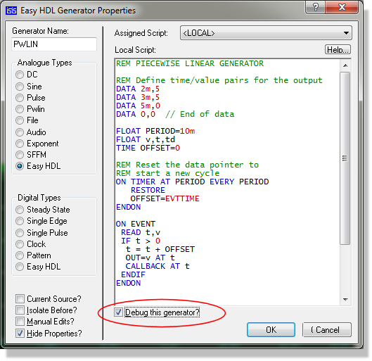
Simple Triangle Wave Generator in EasyHDL specified as active for debugging
See Also:
Scriptable Generators, for the EasyHDL language and its command reference.