ATTACHING A SPICE MODEL
Overview
A SPICE model is bound to a schematic component by a small set of device properties. Five properties are involved, of which any given component uses three or four:
| Property | Purpose |
| PRIMITIVE | Declares that the component is simulated by SPICE, and says which kind of SPICE device it is. Always required. |
| SPICEMODEL | Names the model or subcircuit to use, and optionally the file that contains it. Always required. |
| SPICEFILE | Names the ASCII file that contains the model, where it has not been given as part of SPICEMODEL. |
| SPICELIB | Names the binary SPICE model library that contains the model, as an alternative to SPICEFILE. |
| SPICEPINS | Binds the pins of the schematic part to the nodes of the model. Needed for subcircuit models only. |
Whichever of these properties names a file, that file is looked for in the design's own folder first, and then in each of the folders listed under System > System Settings in the field User Simulation Model and Module Folders. This search order applies equally to SPICEFILE, to the file named in the second field of SPICEMODEL, to the library named by SPICELIB and to any file brought in by an .INCLUDE card.
The worked examples in this topic all use the file SPICEMOD.LIB, which is supplied in the Graph Based Simulation folder of the samples rather than in the Models folder of the installation. They work because the design's own folder is searched first. If you keep a model file next to the design that uses it, you never need to touch the folder list at all.
PRIMITIVE
The value of this property is two fields separated by a comma. The first field declares the class of the component and the second names the device type. For a component modelled by a SPICE subcircuit the assignment is always:
PRIMITIVE=ANALOGUE,SUBCKT
It signifies that the component is to be simulated directly by SPICE3F5, and that it is represented by a subcircuit rather than being an actual SPICE primitive.
Neither the case of the value nor the choice between the spellings ANALOG and ANALOGUE makes any difference; the first field is not examined for an analogue device and the second is matched without regard to case.
There must be no space after the comma. A space becomes part of the device type, which then fails to match anything, and the simulation stops with a message of the form "U1 - device type ' SUBCKT' not recognized!".
Primitives for model card devices
Where the device is described by a .MODEL card rather than a subcircuit, the second field names the SPICE primitive that the model card is parameterising:
| Second field | Device |
| DIODE | Diode |
| NPN, PNP | Bipolar junction transistor |
| NJFET, PJFET (NJF and PJF are also accepted) | Junction field effect transistor |
| NMESFET, PMESFET | MESFET |
| NMOSFET, PMOSFET | MOSFET using the default level |
| NMOS1, NMOS2, NMOS3, NMOS6, NBSIM1, NBSIM2, NBSIM3 and the PMOS and PBSIM equivalents | MOSFET at a specific model level |
| TRANLINE | Lossless transmission line |
| LOSSYLINE | Lossy transmission line |
| URCLINE | Uniformly distributed RC line |
| VSWITCH, CSWITCH | Voltage controlled and current controlled switch |
| SUBCKT | Subcircuit defined by a .SUBCKT card |
The level of a MOSFET model is selected by the primitive you choose, not by a LEVEL= parameter on the model card. A model card written for level 3 must be attached to a component whose primitive is NMOS3 or PMOS3.
The parameters accepted on the model card are in each case the standard Berkeley SPICE3F5 set for that device, and the Berkeley user guide is the authority on their names and meanings.
SPICEMODEL
This property names the model or subcircuit to use, and optionally the file that contains it:
SPICEMODEL=LMC660,SPICEMOD.LIB
The two fields may be separated by a comma or by a space, so the following is equivalent:
SPICEMODEL=LMC660 SPICEMOD.LIB
If the filename is left out, the file must instead be named by SPICEFILE or the library named by SPICELIB, or the model must be present in a SPICE script on the schematic.
The model name must match the text used in the model file exactly. If the subcircuit is called LMC660/NS you must include exactly that text, suffix and all. Case, on the other hand, is not significant: model names are matched without regard to case.
To find the name, open the model file in a text editor and look for its .SUBCKT or .MODEL card. The name is the first item after the card:
.SUBCKT LMC660 1 2 99 50 41
SPICEFILE
This property names the ASCII file that contains the model, where the filename has not been given as the second field of SPICEMODEL:
SPICEFILE=SPICEMOD.LIB
Some manufacturers supply many models in one file and others supply one file per model. It makes no difference which. SPICE files are found with a variety of extensions, .TXT, .CIR, .LIB and .MOD among them, and you must give the extension explicitly.
If you leave the extension off, .MOD is assumed. This catches people out with files that are really .TXT or .LIB: the file will not be found, and the simulation log will name a file you did not ask for.
SPICELIB
This property names a binary SPICE model library that contains the model, and is used instead of SPICEFILE:
SPICELIB=NATOA
Give the library name without its extension. The supplied libraries are the .SML files in the Models folder of your installation, and NATOA.SML in the example above is the one that holds the National Semiconductor op-amps. See SPICE Model Libraries below for what these files are and why they exist.
SPICEPINS
This property lists the pin names of the schematic part in the order in which the corresponding nodes appear on the model's .SUBCKT card:
SPICEPINS=POS IP,NEG IP,V+,V-,OP
It is vital that this is correct, because nothing else determines which pin of the part drives which node of the model. It applies to subcircuit models only; a device described by a model card has its pins assigned by its primitive and needs no SPICEPINS property. If the property is absent, the pin order of the schematic part is used instead.
You need to know the pin names of the part, which are often hidden. These can be established by moving the mouse over the pin ends of the component and reading the status line.
Do not leave spaces immediately before or after the commas. The list is split on the comma alone, so a leading or trailing space becomes part of the pin name and stops it matching. Pin names that themselves contain a space, such as POS IP, are perfectly acceptable. A name that does not match produces the warning "Pin POS IP of U1 referenced but not found in SPICEPINS property" in the simulation log, and the model is then bound to the wrong nodes.
Adding the Properties with Make Device
The properties are added to the component through the Make Device wizard, which writes them into the library part so that every copy of the part you place carries them. The worked example below attaches the LMC660 op-amp model held in SPICEMOD.LIB to an op-amp part with the pins POS IP, NEG IP, V+, V- and OP. The finished result is the sample design Spice1.pdsprj.
- Place the part on a blank schematic and run the simulation. Since the part carries no simulator model yet, the simulation log opens with an error.
- Close the simulation log. Put a copy of SPICEMOD.LIB in the folder that holds your design, or in one of the folders listed under System > System Settings in the field User Simulation Model and Module Folders.
- Right click the device and select Make Device from the context menu. Click Next until you reach the Component Properties & Definitions page.
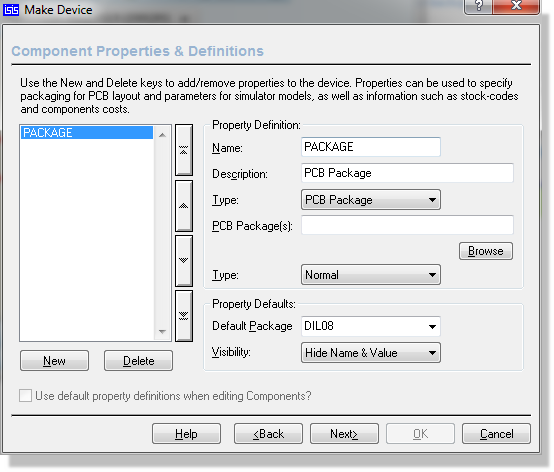
The Component Properties & Definitions page of the Make Device wizard
- Click New to create a property definition.
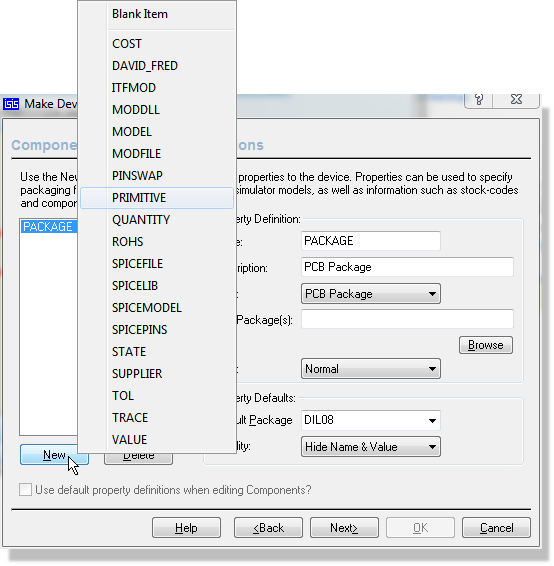
Creating a new property definition with the New button
- Type the property name into the Name field, leave Data Type set to String, and enter the property value in the Property Defaults section. The supplied library parts declare their SPICE properties with Mode set to Hidden so that the values do not clutter the schematic, and you will normally want to do the same.
- Add the first property, PRIMITIVE, with the value ANALOGUE,SUBCKT.
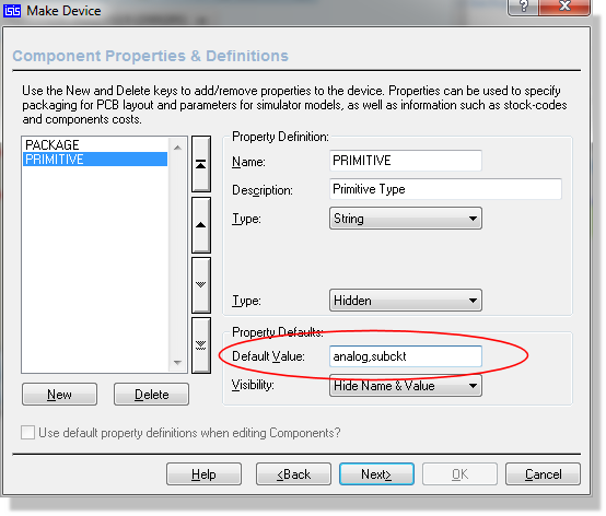
The PRIMITIVE property, defined with the value ANALOGUE,SUBCKT
- Add SPICEMODEL with the value LMC660, which is the name on the .SUBCKT card in the model file.
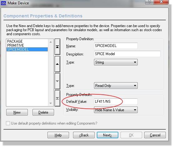
The SPICEMODEL property, carrying the name of the subcircuit
- Add SPICEFILE with the value SPICEMOD.LIB, including the extension.
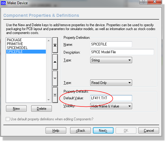
The SPICEFILE property, carrying the name of the file that holds the subcircuit
- Add SPICEPINS with the value POS IP,NEG IP,V+,V-,OP, which is the pin order given by the comment block at the head of the model.
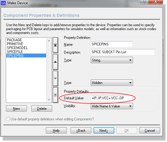
The SPICEPINS property, listing the pin names in model node order
- Click Next and complete the creation of the device into one of your libraries. Two messages follow. Click Yes on the first to update the library part.
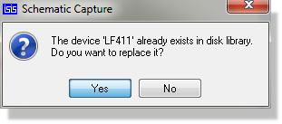
Confirming that the existing library part is to be replaced
- Click OK on the second to pull the updated part back into the schematic and update the copies you have already placed.
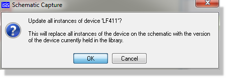
Updating the parts already placed on the schematic
- Run the simulation again. It will now run to completion.
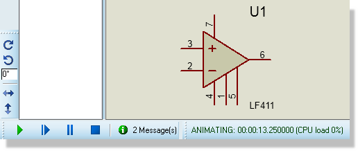
The simulation log after a successful run
What to do if the simulation still reports an error
Using a SPICE Subcircuit (SUBCKT definition)
Our first worked example is the LMC660 op-amp model held in the SPICE file SPICEMOD.LIB. It is supplied as the design Spice1.pdsprj in the Graph Based Simulation samples folder.
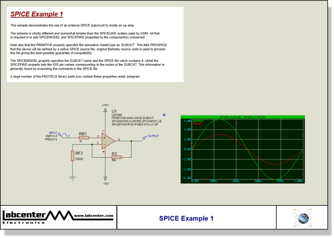
The sample design Spice1.pdsprj, in the Graph Based Simulation samples folder
The op-amp component has been given three property assignments:
PRIMITIVE=ANALOGUE,SUBCKT
SPICEMODEL=LMC660,SPICEMOD.LIB
SPICEPINS=POS IP,NEG IP,V+,V-,OP
The filename could equally have been given separately, which is the form the walkthrough above uses:
SPICEMODEL=LMC660
SPICEFILE=SPICEMOD.LIB
The SPICEPINS value comes from the comment block at the head of the model file:
* connections: non-inverting input
* | inverting input
* | | positive power supply
* | | | negative power supply
* | | | | output
* | | | | |
.SUBCKT LMC660 1 2 99 50 41
The diagram lists the pin functions and their ordering on the .SUBCKT line. The numbers themselves relate to the internals of the model definition and are not relevant to our purpose. The key information is that the non-inverting input is the first node, the inverting input the second and so on, and that is what determines how you construct the value of the SPICEPINS property: you give the pin names of the schematic part in the corresponding order.
Using a SPICE Model (MODEL card)
For semiconductor devices, specifically diodes, transistors, JFETs, MESFETs, MOSFETs and the controlled switches, SPICE models are usually specified as a single .MODEL card that lists the parameter values for the appropriate SPICE primitive. The procedure is similar to that for a subcircuit model but a little simpler, because the question of pin name translation does not arise. Schematic library parts already exist for the various types of SPICE primitive and you will find them in ASIMMDLS.LIB.
Our second worked example is a 2N2222 transistor, supplied as the design Spice2.pdsprj in the Graph Based Simulation samples folder.
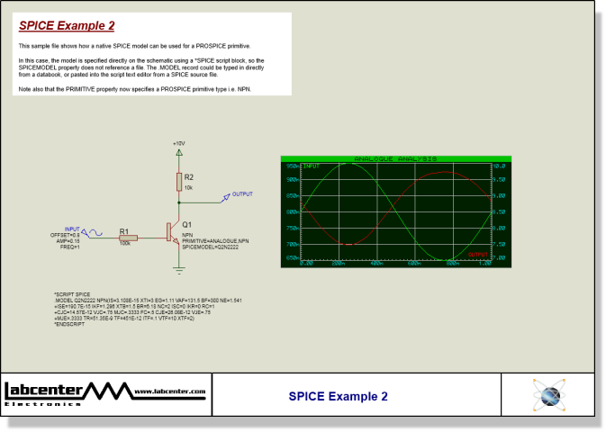
The sample design Spice2.pdsprj, in the Graph Based Simulation samples folder
The transistor has been given two property assignments:
PRIMITIVE=ANALOGUE,NPN
SPICEMODEL=Q2N2222
The first indicates that the device is to be simulated directly by PROSPICE as an NPN type primitive. If you pick a diode, transistor, JFET or MOSFET from the ASIMMDLS library it will have the appropriate PRIMITIVE assignment already in place.
The second specifies the name of the model to use. It carries no filename because in this design the model card is typed directly onto the schematic as a SPICE script, as described in SPICE Scripts below. Had the same model been taken from a file instead, the assignment would have read:
SPICEMODEL=Q2N2222,SPICEMOD.LIB
Most manufacturers supply many model card definitions in a single file, so this form is the usual one.
SPICE Model Libraries
The third party SPICE model libraries supplied with PROSPICE are held in binary library files, similar to the device and symbol libraries used by the schematic. We have done this for two reasons:
- Many model files are extremely small and very numerous, and would waste a great deal of space on disks with large cluster sizes if they were stored individually.
- When many models are held in a single ASCII file, PROSPICE has to parse the whole file in order to use just one model, which is relatively slow.
Where a model is held in a SPICE model library, the syntax for binding it to a schematic library part is slightly different. The LMC660 of the first example would instead carry:
PRIMITIVE=ANALOGUE,SUBCKT
SPICEMODEL=LMC660
SPICEPINS=POS IP,NEG IP,V+,V-,OP
SPICELIB=NATOA
The first three assignments are unchanged. SPICELIB replaces SPICEFILE and gives the name of the model library that contains the part. The supplied libraries are the .SML files in the Models folder of your installation; between them they hold many thousands of manufacturers' models.
SPICE Scripts
You can also type SPICE model definitions directly onto the schematic as a script block, and then call the models up from the relevant components. This is what the Spice2.pdsprj sample does. The transistor model for the 2N2222 is entered as follows:
*SCRIPT SPICE
.MODEL Q2N2222 NPN(IS=3.108E-15 XTI=3 EG=1.11 VAF=131.5 BF=300 NE=1.541
+ISE=190.7E-15 IKF=1.296 XTB=1.5 BR=6.18 NC=2 ISC=0 IKR=0 RC=1
+CJC=14.57E-12 VJC=.75 MJC=.3333 FC=.5 CJE=26.08E-12 VJE=.75
+MJE=.3333 TR=51.35E-9 TF=451E-12 ITF=.1 VTF=10 XTF=2)
*ENDSCRIPT
The transistor's SPICEMODEL property is then simply:
SPICEMODEL=Q2N2222
with no filename given. The whole of the script block is placed at the head of the deck before anything else is processed, so anything you can write in a model file you can write here.
This route is most useful where a model has been obtained on paper, or where you want to experiment interactively with the parameter values.
Script blocks on the schematic
See Also: