WHEN A SPICE MODEL WILL NOT SIMULATE
Overview
When a SPICE model fails, it almost always fails while the deck is being assembled rather than during the simulation itself, and it says so in the simulation log. The messages are specific, and each of them points at one particular mistake.
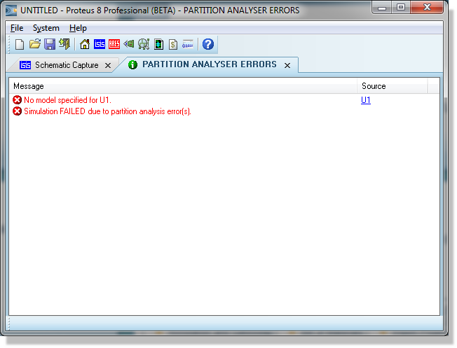
The simulation log reporting a part with no simulator model attached
Diagnostic Messages
The table below lists the messages produced when a model cannot be linked, together with what each one means and what to do about it. Where a message carries a name in the running system, it is shown here in angle brackets.
| Message | What it means | What to do |
| cannot open SPICE source file <file> | The file named by SPICEFILE, or by the second field of SPICEMODEL, was not found anywhere on the search path. | Check the spelling and, in particular, the extension: if you leave the extension off, .MOD is assumed. Put the file in the folder that holds the design, or add its folder to the list under System > System Settings. |
| Cannot find library model '<name>' | The model library named by SPICELIB was opened, but it holds no model of that name. | Check the model name against the library contents, and check that SPICELIB names the right .SML file. This message is reported on the SPICE model linkage trace channel. |
| SUBCKT '<name>' used in '<component>' but not found. followed by Failed to expand subcircuits. | The model file was read, but it contains no .SUBCKT card of the name given by SPICEMODEL. | Check that the name matches the .SUBCKT card exactly, suffix and all. If it does, the card was probably discarded because the file uses a construct that is not accepted. The first message is reported on the SPICE model linkage trace channel; the second always appears. |
| Pin <pin> of <component> referenced but not found in SPICEPINS property | A name in the SPICEPINS list does not match any pin on the schematic part. | Almost always a space immediately before or after one of the commas. Otherwise the pin name is wrong: hover over the pin ends of the part and read the real names from the status line. |
| <component> - device type '<type>' not recognized! | The second field of the PRIMITIVE property is not a known device type. The simulation stops. | Almost always a space after the comma, which becomes part of the device type. Otherwise check the second field against the table of primitives. |
| Model <name> specified but not found in <component>. | The component names a model card that is not present in the assembled deck. | Check the model name, and check that the file or script that defines the model card is actually being linked. |
| Illegal continuation line: ignored. | A line beginning with a plus sign appears where there is no preceding line for it to continue. | Usually the result of a partial paste, or of the preceding line having been dropped. Check the head of the model text. |
Unsupported Constructs
If a third party model does not work, the first thing to check is that it was actually written for SPICE 2 or SPICE 3. Models developed for PSPICE™ can include all manner of elements and syntax constructs that are not standard SPICE.
The two you are most likely to meet are .LIB, which pulls in another file, and .PARAM, which declares a symbolic value used later in the file. Neither is accepted, and nor are .FUNC, .STEP, .SAVE, .INC, .GLOBAL or .MC. Note also that there is no A card, so a model built on XSPICE code models cannot be used at all.
The full list of what is and is not accepted, together with the device letters recognised, is given in Understanding SPICE Models. It is worth reading that list before spending time on a model that cannot work.
Polynomial sources and PSPICE™ VALUE= sources are not on the unsupported list: they are translated automatically, along with the LOG and LOG10 difference between the two dialects.
Tracing the Model Linkage
The fastest way to establish what the simulator actually did with your model is to turn on the SPICE model linkage diagnostic. Select Configure Diagnostics from the Debug menu, find SPICE model linkage among the global simulator diagnostics and set its trace level to Warnings Only or higher.
With the channel enabled the simulation log reports which files were read, which library models were loaded and from which library, any card that was rewritten during translation, and the two linkage warnings noted in the table above. It is the quickest way to confirm that the file being read is the file you think it is, which matters because the design's own folder is searched before the folder list.
Model Design and Circuit Design
Subcircuit models vary greatly in complexity and in design, and as a result some are much easier to simulate than others. As a general rule, if PROSPICE could not simulate your circuit with its translated model, then not much else could either.
We have often found that the problem is greatly worsened by poor circuit design. If you have an application note for the device, compare it with your circuit to see whether, for example, you are allowing enough input current to bias the input stage successfully. The model designer almost certainly made the model work with circuits similar to those in the application note rather than in the general case.
Convergence Problems
A model that links correctly but produces a singular matrix, a timestep too small error or a failure to converge is a different problem, and the tactics for dealing with it, GMIN included, are given under Convergence Problems in the Troubleshooting chapter.
What that topic does not say is where to set these values. Any SPICE option, GMIN included, can be set in either of two places: as a property on the design carrying the same name as the option, which then applies to the whole design; or for one graph at a time, by editing the graph and clicking the SPICE Options button.
See Also: