WORKING WITH ARDUINO
Introduction
Arduino is an extremely popular electronics environment consisting of ready-made circuit boards (shields and breakouts) and comprehensive software libraries that make it easy to drive them. Proteus supports Arduino simulation through our support of the required AVR models and our huge libraries of embedded peripheral models mean that we can also simulate most of the shields and breakout boards as well.
Simulation of the classic AVR based boards is provided by our AVR processor models. More complex boards, such as the Arduino Uno R4, are simulated by a native Arduino VSM model in which the Arduino core itself executes directly inside the simulator rather than on a simulated processor. This all happens behind the scenes; the workflow in VSM Studio is the same whichever board you choose.
Since we have all of the technology we've put quite a bit of time into making working with Arduino in Proteus as simple and intuitive as possible. This means that working in VSM Studio with Arduino can be much different from working with other processor targets, as described in the topics below.
The peripheral driver system described here is not limited to Arduino: driver sets also ship for Arduino STM32, MicroPython and Raspberry Pi. The MicroPython workflow is described in the MicroPython manual.
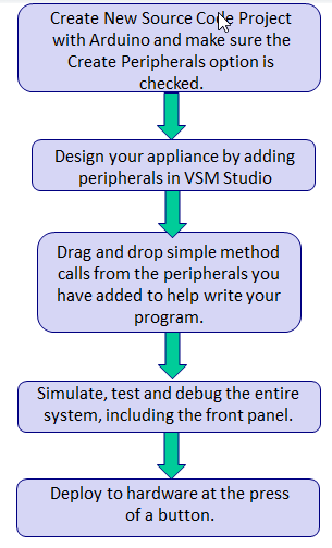
Summary workflow for Proteus VSM for Arduino with the VSM Studio IDE.
New Project Wizard
In the New Project Wizard the default options will suffice until the firmware page when we want to select the Create Firmware Project option. The target family is Arduino (not AVR) and let's choose the controller as the Arduino Uno. The other important options are Create Quick Start Files and Create Peripherals; make sure that both are selected. The Compilers button beside the compiler list opens the Compilers dialogue, so that a toolchain can be installed or configured without leaving the wizard.
The third mode on this page, Create Flowchart Project, is the Visual Designer route, in which the program is drawn as a flowchart rather than written as a sketch. See the Visual Designer manual for that workflow.
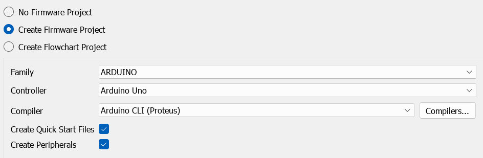
The Create Peripherals checkbox is vital here as it will allow you to choose from all of the prepared shields and breakout boards and will initialise all of the Labcenter peripheral drivers that work with them. If this box is unchecked you can still work with Arduino but will have no access to the Labcenter peripheral drivers in VSM Studio.
Default settings for the rest of the New Project Wizard are then fine.
All Arduino boards build through the Arduino CLI (Proteus) toolchain, which is included with Proteus. The compiler and board core for the selected board are downloaded from the Labcenter servers and installed automatically the first time the project is built, so no toolchain setup is required. The platform and its pinned version can be inspected on the Controller tab of the Project Settings dialogue. See the Compilers topic for more detail.
Once complete, you will end up with a source code project in VSM Studio which includes a sizeable amount of pre-generated code.
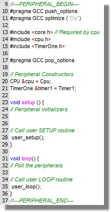
Those who work with MFC or similar will find this familiar but the key thing is not to disturb, change or move the generated code. This is used by the Labcenter drivers and will update as you add peripherals so needs to be managed by the Proteus software. You should ignore this section of code and write your code inside the setup() and loop() routines as normal.
On the schematic you will find a pre-placed Arduino Uno. The board appears because the Autoplace processor option on the wizard page was left selected; clear that option if you would rather place the board yourself.
Design Phase
The first thing to do now is to browse and add your shields and breakout boards. We've simplified this by adding an 'Add Peripheral' command to the Project menu and the right click context menu on the project tree. Beside it you will find Add IoT Control, which adds a control to the project's IoT panel; panels are covered in the IoT Builder manual.
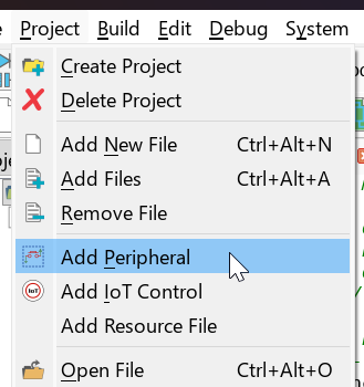
This presents you with a peripheral gallery, which the form itself titles Select Project Clip. The peripherals are grouped by category and the Category list at the top of the form narrows the gallery to one category at a time; breakout boards, Grove modules and Adafruit shields are among the categories provided.
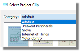
You can add these to your project by selecting them and clicking the Add button or by double clicking. For a simple test we'll add a momentary action push button and an LED from the breakout peripherals category.
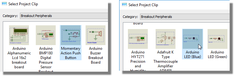
These will then appear both in the project tree in VSM Studio and will be placed for you on the schematic.
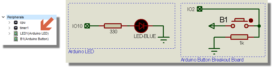
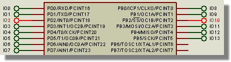
Connectivity is achieved on the schematic by terminal so in our case the button is connected to IO2 and the LED is connected to IO10.
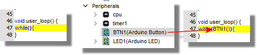
In our firmware, we can see a number of methods for controlling the LED but there are no extra methods for the button. We can drag and drop these methods onto the source code to help us control the peripherals. Let's say we want to turn the LED on while the button is down. We start our while loop and then simply drag from the button in the project tree and drop onto the source code.
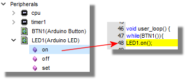
Inside our while routine we want to turn the LED on. This time hold the CTRL button down and drag and drop the on method of the LED. Note that the caret moves as you move the mouse so that you can position wherever you like.
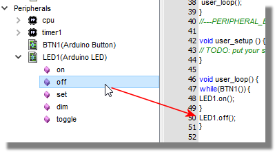
Finally, we need to turn the LED off outside the while loop. Again we can just drag and drop the off method into the correct place in our program.
That's it. Obviously a trivial example but the same principles hold true whether it's an LED, a BLDC motor or a TFT display.
Summary:
- Don't change or move the generated code at the top of the file.
- If you drag and drop normally the code snippet will insert wherever the mouse caret is in the file.
- If you hold the CTRL button down while dragging then the mouse caret will move with the drag and the code snippet will be inserted at the caret position when you release the mouse.
Working without Labcenter Drivers
You may decide that you don't want to use the Labcenter peripheral drivers or that you want to create your own shield / add electronics to the schematic etc. In cases like this you should de-select the Create Peripherals checkbox in the New Project Wizard.
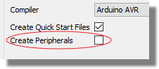
You will end up with a blank sketch (no pre-generated code) and you will have to add any shields etc from the Import Project Clip command on the File menu on the schematic.
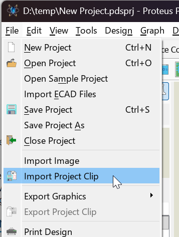
When you do this you will not get the Labcenter drivers for that peripheral and will have to code your program at the level of Arduino C++. This may provide extra flexibility but is less simple. The EDAi assistants are available from inside VSM Studio and can give you code-level guidance on the sketch you are writing, so consult the EDAi manual as you work.
If you maintain your own peripheral drivers, the Reload Driver command on the peripheral's right click context menu in the project tree re-reads that peripheral's descriptor from its XML file, so that edits made to the driver are picked up without recreating the project.