Tutorial 3 : Motor Control
Introduction
This tutorial shows how you can easily control both DC motors and Stepper motors with Visual Designer. We'll do this using the Adafruit DC and Stepper motor hat for Raspberry Pi.
Setup
Start by creating a new Visual Designer Project and then Add the Raspberry Pi Hat with DC and Stepper Motors from the peripheral menu.
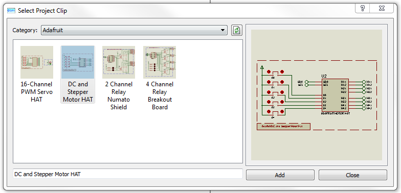
Picking the Adafruit Hat from the Add Peripherals command in Visual Designer
Unlike the Arduino Hat the Raspberry Pi Hat lets you connect the motors yourself. This means you need to first find the motors via the schematic pick devices form (MOTOR-DC & MOTOR-BISTEPPER) and double click to insert them into the project.
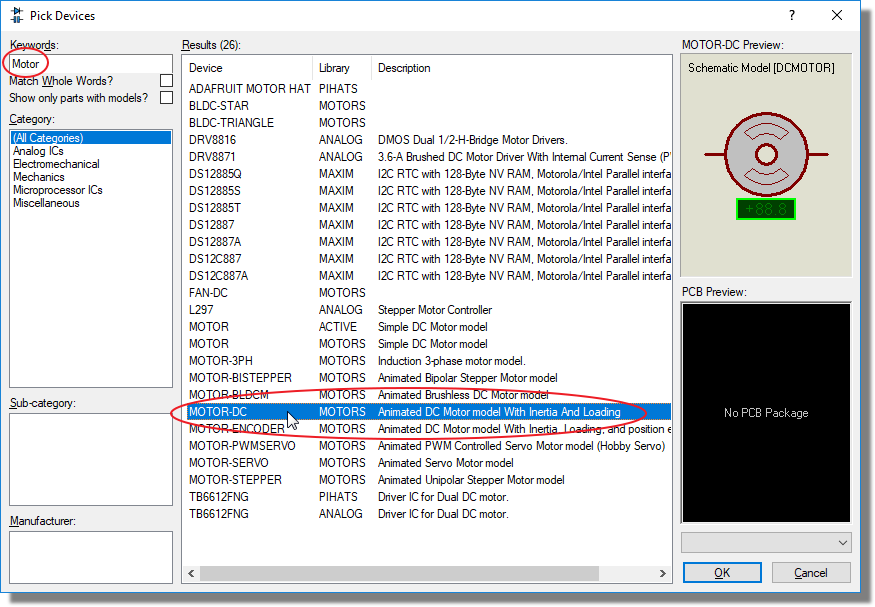
Using the Pick Devices Dialogue on the Schematic to add the motors to your design.
Then connect the part to the hat using the terminals The usual rules apply in that terminals with the same name are deemed connected together
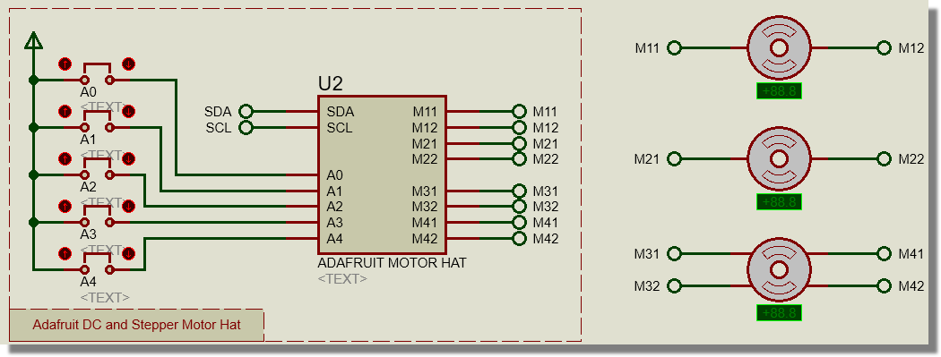
Here you can see we have connected one stepper motor and two DC motors with connections made by terminals.
Programming
For this project we will have 2 buttons, one will start a dc motor and the other will stop that motor. After we have this project working we will then simulate it and work with the debugging tools.
Firstly, you will need 3 components, 2 buttons and a motor. Add the two buttons using the add peripheral method.
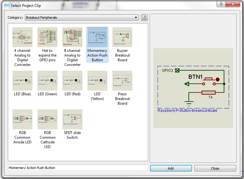
Add Button Peripheral.
Make sure you change the GPIO pins so that they are not both using the same pin
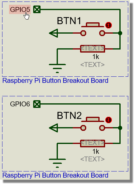
Make sure the buttons are assigned to unique GPIO Lines
You should already have at least one DC motor. If not then make pick one from the libraries and make sure it is connected to motor 1 (M11,M12) of the hat. It should look something like this:
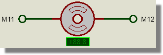
Correctly connected DC Motor on Motor 1 of the Hat.
Note that if you want the motor to appear in Visual Designer during simulation you will need to draw an Active Popup box around the motor.
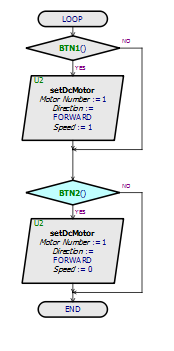
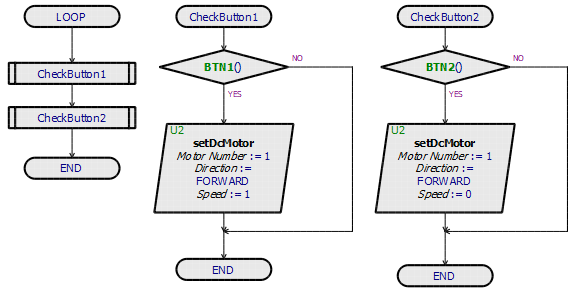
Now you can drag the code blocks on. We want to change the speed of motor 1 each time a button is pressed. Button 1 will start the motor and button 2 will stop the motor. You won’t need any code in setup. Your finished program should look like the following
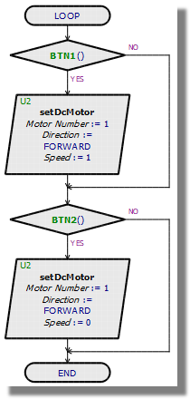
Motor Control flowchart. Uses the sensor functions for the buttons to make decisions.
Testing and Debugging
Now that the project is ready to go we can test it out in simulation. The remainder of this tutorial is essentially a detailed look at simulation and stepping commands to make sure that you understand how to control a running simulation and how you might debug problems with your code.
The simulation is controlled from the animation control panel at the bottom left of the Proteus application
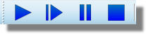
Here you will find the play, step, pause and stop buttons. The play button will start the project or continue if the project is paused.
The step button will allow you to slowly step through the project pausing after every block of code.
The pause button will pause time allowing you to look at variables, voltages and other elements. The pause button will not stop the project and you can restart it with the play button.
The stop button will stop the whole project and allow you to edit and modify it.
Basic Single Stepping
We will start by simply pressing run, the program will start, and you will enter simulation mode. Press button one to start the motor going. Let the motor gain some speed then press button 2 to stop power to the motor. The motor will now slow down. Once you have tested this and confirmed that everything is working properly you can stop the program using the stop button.
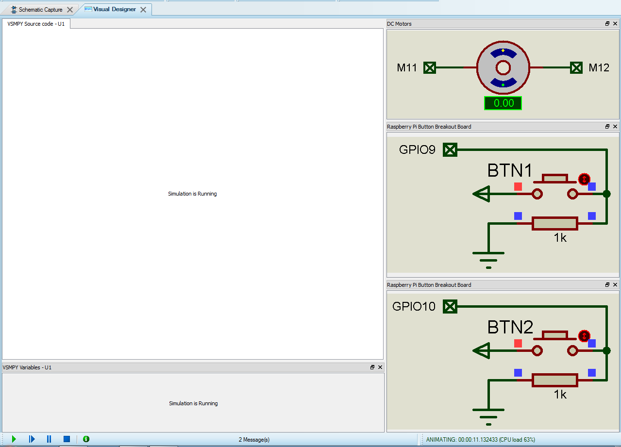
Next, press the step button once to start then pause the program. At this stage the program code is currently sat in the setup block. Next, pres the Step Into button to get to the end of the Setup block:
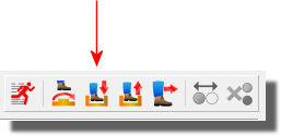
You will now see the End of setup light up. This shows that the setup function has ended.

Pressing the Step Into button again will advance the program to the first decision block of the loop routine.
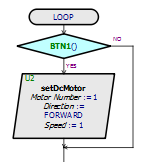
If button 1 is pressed the code will follow the 'Yes' line, if its not pressed it will follow the 'No' line. In our case the button is not pressed so when we keep stepping the code the program will move through to the next decision block. We'll then continue running around this loop routine until a button is pressed.
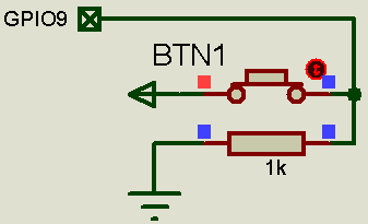
Finally, note that you can lock a button in place by pressing the red vertical arrows in the side of it. This way it will be held down even when you take your mouse away

Stepping and Routines
Let's look now at how the step into and step out debugging commands work when we have sub-routines in our program. These basically navigate us in and out of the program stack.

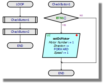
To help explain, we have modified our program to include a couple of sub-routine calls.
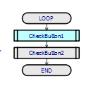
In this new program you can step through however it will only highlight the event call and not enter the event block. It will jump between CheckButton1, CheckButton2 and End without entering the two events. If you do want to enter an sub-routine wait until the event is highlighted.
Then press step into to enter the routine and highlight the first code block in the routine.
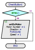
We could continue to step through the routine with our normal step commands or use the step out button to exit the routine and pause at the next code block following the return from the routine.
Breakpoints
Breakpoints allow you to stop the code when it reaches a specific block of code. To toggle breakpoints, enter Visual designer, right click on the block you wish to place the breakpoint and toggle breakpoint.
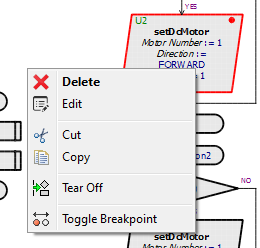
Now run the program, assuming button 1 is up nothing will happen. The code will run normally until you press button 1. Once button 1 has been pressed the code will pause on that block.
From here you can step through the code to debug further.
Debugging Generated Code
If you want to look deeper into what is happening in the code you can look directly at the code and not the blocks. Right click on the project menu and select debug generated code.
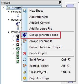
Now when you run the project the flowchart won’t be present. Instead there is a blank screen. By pressing the step button once it will load up the python script. Now every time you step it will step line by line opposed to block by block.
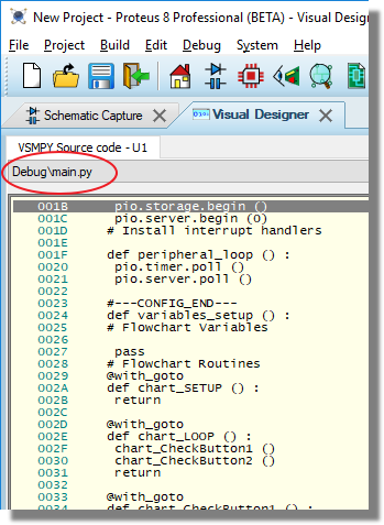
You should now be able to navigate and follow the code using the same debugging and stepping tools we discussed earlier. To navigate through different routines, use the dropdown box above the code.
Note about Addresses
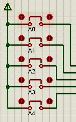
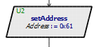
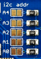
Some hats are stackable such as this motor hat. When using multiple hats together you may need to change the I2C addresses. You can do this by using the jumpers. The Hat will have a base address, for the motor hat the base address is 0x60. The Jumpers work in binary so by connecting A0 the address will go to 0X61, and connecting A1 the address will go to 0x62 and so on. The motor hat has a possibility of 32 different addresses including address 0x60.