Appendix: Lesson Plan Example
Introduction
This appendix walks through a complete lesson plan authoring session. The example uses a 555 timer circuit that is already wired and ready for investigation, so the lesson focuses on measurement, analysis and calculation rather than construction. This is a common pattern: the teacher has an existing lab exercise that works well, and the authoring conversation formalises it into a structured lesson plan with validation criteria, progressive hints and a scoring rubric.
The walkthrough shows the two authoring stages in sequence. In a Creating session the teacher and the assistant agree the shape of the lesson, and in the Testing session that follows, the teacher works through the exercise as a student while the assistant captures the expected values from the live simulation.
This exercise ships with Proteus. Open 555 Oscillator from the ProTutor Lesson Examples folder under Samples to see the finished lesson plan and run it as a student would. The CAN sample projects also contain lesson plans, shipped switched off, which you can enable from Project Settings if you want to explore them. You will need an AI model configured with your own API key, since the lesson itself is delivered by the assistant.
See Also:
Worked Example: Authoring a 555 Timer Lesson
The Starting Circuit
The exercise uses a 555 timer (U2) configured as an astable oscillator with a 12V supply. The timing network consists of R3 (6k3) as the charge resistor, R2 (10k) as the discharge resistor, and C1 (1u) as the timing capacitor. A potentiometer RV1 (1k) is connected to the control voltage pin (CV, pin 5), allowing the student to adjust the comparator thresholds. The discharge pin (DC, pin 7) connects between R3 and R2, and the threshold (TH, pin 6) and trigger (TR, pin 2) pins are connected together at the R2/C1 junction.
This circuit is distributed to students fully wired. The lesson focuses entirely on observation, measurement and analysis rather than construction.
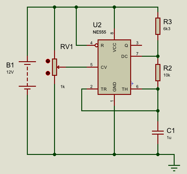
The 555 Timer astable circuit used for the lesson plan example, showing U2 (NE555) with R3, R2, C1, RV1, and the 12V supply.
Creating the Structure
The teacher opens the project in Proteus, opens the settings dialogue, ticks Tutor Mode and clicks New Lesson Plan... They fill in the title, audience and duration, and Proteus creates an empty plan and switches the chat into a Creating session.
In that session the teacher describes the exercise, attaching the PDF of their existing lab worksheet so that the assistant can work from it. The assistant proposes a structure of eight steps, each with a type, an instruction and a criterion for completion. The teacher adjusts the wording and the order, and the skeleton is committed. A Testing session opens automatically.
The Testing Session
The teacher now works through the exercise as a student would, using the System Meter to take the readings, while the assistant plays the runtime tutor and records what it needs. The following table summarises the eight steps, showing the step type and what gets captured during the rehearsal.
| Step | Type | Question or Task | What Gets Captured |
| 1 | observe_and_identify | Run the simulation with a voltmeter on the capacitor node. What do you see on the meter? | The student observes the meter flickering or changing too fast to read a stable value. This becomes the expected observation, with key concepts: flickering, too fast to read. |
| 2 | analyse | Why does the meter flicker? What change to C1 would fix it? What stays the same? | The expected answer explains that the period is proportional to RC, so increasing C1 to 100uF slows the oscillation by a factor of 100. The thresholds remain unchanged because they are set by the CV pin, not by C. |
| 3 | configure | Change C1 to 100uF. Report the minimum and maximum voltages on the capacitor node. | The teacher changes C1 and reads the meter. The actual simulation values, approximately 3.0V minimum and 6.2V maximum, become the expected range with appropriate tolerances. |
| 4 | measure_and_record | Adjust RV1, reset the min/max readings, and report the new thresholds. Why did they change? | The new threshold values, and the expected explanation: both thresholds shift together because RV1 controls pin 5 (CV), which sets the comparator reference levels inside the 555. |
| 5 | measure_and_record | Reset the pot to centre. Switch the meter to measure Vab across R2 and report the peak positive and negative values. | The teacher measures approximately +5.5V and -6.1V. These become expected ranges, along with the measurement methodology: the meter goes across R2, not to ground. |
| 6 | analyse | Why does Vab swing positive and negative, and why are the magnitudes not equal? | The expected answer explains that current reverses direction between charge and discharge cycles. During charging, R3 is in series with R2 so the voltage across R2 is reduced; during discharge, current flows through R2 alone so the magnitude is larger. |
| 7 | calculate | Predict the peak discharge current through R2. | The expected calculation is 6V / 10k ohm = 0.6mA, the capacitor value being irrelevant to the peak current. The expected range and the formula are both recorded. |
| 8 | analyse | Switch the meter to measure Va at pin 3 (the output). Why does it swing 0 to 12V when the capacitor voltage is only 3 to 6V? | The expected answer explains that pin 3 is a digital flip-flop output that snaps rail-to-rail; it does not follow the capacitor voltage. Key concepts cover the internal comparator and flip-flop. |
What Happens at Each Step
For each step in the rehearsal, the assistant:
- Presents the instructions exactly as a student would see them, so the teacher can judge the wording and level.
- Watches the teacher working in Proteus, reading meter values, checking probe placement, and noting component changes.
- Sets expected value ranges from the actual simulation results, with realistic tolerances, typically 10 to 20% for analogue measurements.
- Asks the teacher about common student mistakes and the appropriate hint level for that step.
- Writes progressive hints: the first redirects attention without giving anything away, and the last makes the answer achievable without stating it outright.
- Generates the guidance that controls how the tutor will behave when delivering this step to real students.
The teacher can interject at any point without breaking the rehearsal by typing a note in square brackets, and can click a step on the progress bar to jump back and revise it.
Review and Finalisation
After working through all eight steps, the assistant presents the complete lesson plan for review. The teacher checks the student-facing text, adjusts the scoring rubric by distributing 100 marks across the eight steps according to their importance, and decides whether students should see their score at the end of the session.
In this example, the teacher might weight the steps as follows:
| Step | Type | Marks |
| 1 | observe_and_identify | 5 |
| 2 | analyse | 15 |
| 3 | configure | 10 |
| 4 | measure_and_record | 15 |
| 5 | measure_and_record | 10 |
| 6 | analyse | 20 |
| 7 | calculate | 10 |
| 8 | analyse | 15 |
The standing orders that stop the tutor leaking answers are generated along with the per-step guidance. The teacher then unticks Authoring to seal the plan, saves the project, and passes it to a colleague to try as a real student, iterating until satisfied.
Key Observations from This Example
Several aspects of this worked example illustrate the strengths of the rehearsal approach:
- Expected values (3.0V, 6.2V, +5.5V, -6.1V, 0.6mA) came from the live simulation, not from textbook estimates. There is no risk of a mismatch between what the lesson plan expects and what the student observes.
- The teacher naturally identified common mistakes during the rehearsal, such as confusing the capacitor voltage with the output voltage, or forgetting that changing the pot affects the thresholds, and these became hints and context notes in the plan.
- The measurement methodology was captured precisely: which meter mode to use, where to place the probes, across R2 for Vab and at pin 3 for Va, and what constitutes a valid reading.
- Step 7 demonstrates a calculation step where the expected range and the formula are recorded, but the student must work out the answer themselves.
- Steps 2, 6 and 8 are open-ended reasoning questions that are deferred to marking, since they require judgement about the quality of the student's explanation.
See Also: