Working with ProTutor
Introduction
ProTutor is an intelligent assistant built into the Proteus Design Suite and tailored specifically for education. It provides real-time support during schematic design, simulation, and embedded code development, but with a strong emphasis on teaching rather than telling. Designed for use in classrooms and labs, ProTutor guides students through tasks with hints, questions, and conceptual explanations to help them build understanding and confidence.
While it shares the same interface and underlying technology as ProPilot (the commercial version), ProTutor behaves very differently. Rather than providing direct answers or dropping in full code fragments, ProTutor encourages reasoning and learning. It may pose a question in return, suggest a line of investigation, or offer a theoretical recap instead of jumping straight to a solution.
This difference is intentional. ProTutor is designed to work like a virtual lab assistant, not a shortcut. It helps students debug designs, understand hardware-software interaction, and reason through their work, all without undermining academic integrity. Teachers can use Structured Lesson Plans to deliver formal lab exercises with step-by-step validation, progressive hints, and automated marking. Lesson plans are written inside Proteus, in conversation with the assistant, and marking is carried out from the same lesson plan at the end of a session.
See Also:
Ultimately, ProTutor is about helping students think like engineers. It supports independent exploration and problem-solving, while still providing the safety net of a patient, context-aware guide. The following sections will explore how to use ProTutor effectively across schematic capture, simulation, debugging, and code development, whether in open-ended lab work or structured assignments.
Enabling and Disabling ProTutor
To enable ProTutor, click the cog button at the top of the ProPilot chat window.
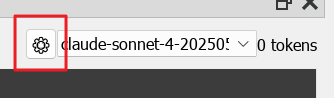
The cog button at the top of the chat window opens the configuration dialogue.
On the Project Settings tab, tick the Tutor Mode checkbox. Tutor Mode is a property of the project rather than of your installation, so it travels with the project file when you distribute it to students.
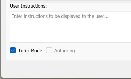
The Tutor Mode checkbox on the Project Settings tab.
If the project contains a structured lesson plan, unticking Tutor Mode discards it. Keep an exported copy of any lesson plan you care about before you change this setting.
To disable ProTutor, clear the same checkbox. The project returns to ProPilot behaviour.
Documentation Help
ProTutor can answer questions about how to use features within Proteus itself in exactly the same way as ProPilot. In this respect the two EDAi assistants are identical.
More Info:
Design Assistance
ProTutor provides intelligent, guided support during circuit design, but unlike ProPilot its goal is not to optimise speed: it is to foster understanding. When a student asks a question, ProTutor does not simply deliver the answer. Instead, it encourages exploration, provides relevant background theory, and offers structured hints to help students work through the problem on their own.
This guided approach is ideal for educational environments, where building reasoning skills is just as important as reaching the correct result. ProTutor might supply a formula for calculating a resistor value or explain the function of a logic gate, but it will often follow up with a 'Now you try it' or 'What do you think this means for the circuit behaviour?' prompt, gently steering students to engage more deeply.
For example, in an analog design exercise, a student might be building an RC low-pass filter and ProTutor will say:
- "This looks like a low-pass filter. Do you remember the formula for the cutoff frequency?"
- "Try calculating it based on the R and C values in your schematic. I will check your answer."
In a digital logic task, such as designing a flip-flop or sequential circuit, ProTutor might support understanding of state transitions and timing behaviour:
- "This is a JK flip-flop. What happens when both inputs are high?"
- "Look at your waveform. Do the outputs match what you would expect from the truth table?"
In an embedded design lab, where students are writing firmware for a microcontroller, ProTutor supports structured thinking without taking over the work:
- "The motor is connected to PB1, so Timer1 is a good choice for PWM. Want to go over how to set up the timer registers?"
- "Try writing the initialisation code yourself; I can help you debug it if needed."
ProTutor works best when students are encouraged to ask questions and try things. It responds in context, using knowledge of the schematic and code to guide the conversation. And importantly, it does not take shortcuts. If a student asks for a direct answer, it may try to encourage initiative:
- "I can help you work through it, but first, what do you think the problem might be?"
This teaching-focused behaviour builds confidence, reduces over-reliance on answers, and mirrors the interaction students might have with a real lab demonstrator or instructor.
Structured Lesson Plans
Structured Lesson Plans are the most powerful way to use ProTutor in the classroom. They transform the AI assistant into a focused, simulation-aware lab demonstrator that guides students step by step through a predefined exercise, validates their work against real expected values, serves progressive hints when they struggle, and builds a detailed record of their progress for assessment.
A structured lesson plan is a JSON document stored inside the Proteus project file. It requires no external database or server infrastructure; the project file is self-contained and can be distributed to students by any mechanism the institution uses, whether that is a network share, an LMS, a USB stick or email. Teachers write lesson plans inside Proteus, working through their own exercise while the assistant builds the plan from what happens, then lock the plan and distribute the project file to students.
How Students Experience a Lesson
From the student's perspective, a structured lesson is a natural conversation with a knowledgeable lab partner. They open the Proteus project distributed by the teacher, and ProTutor greets them and begins working through the exercise. At each step, the Tutor Agent presents instructions, waits for the student to perform the task in Proteus, and validates their work before moving on.
The student types measurements, answers, and observations in plain text. The Tutor Agent responds conversationally: confirming correct answers, asking follow-up questions, or offering a hint if the student is stuck. The underlying validation, hint logic, and progress recording are invisible to the student.
A typical lesson might ask the student to:
- Observe a simulation and describe what they see
- Take measurements using virtual instruments and report the values
- Calculate derived quantities from their measurements
- Wire or modify part of the circuit
- Configure instrument settings
- Write or modify firmware
- Analyse circuit behaviour and explain their reasoning
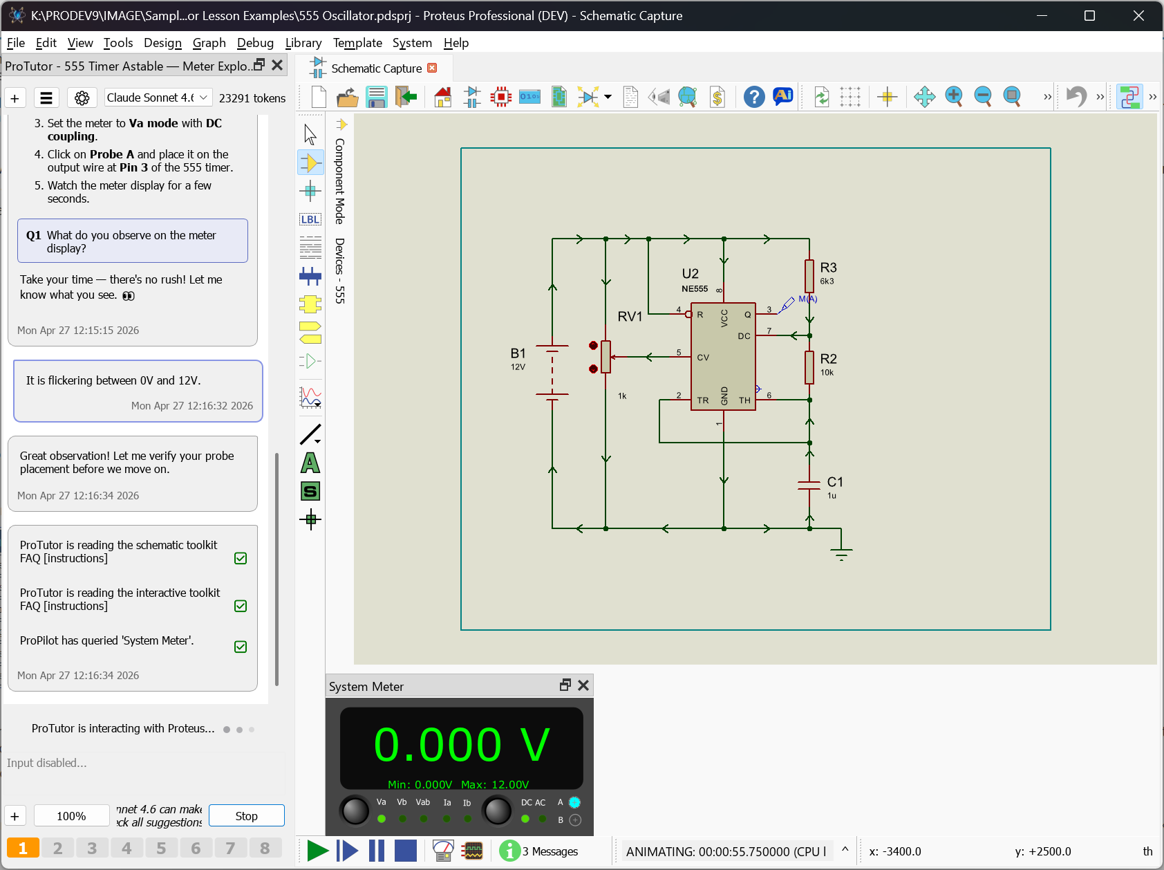
A student session with a structured lesson plan, showing the Tutor Agent presenting a measurement step and validating the student's response.
Step Types
Each step in a lesson plan has a defined type that determines how the tutor presents and validates it. There are seven:
| Step type | What the student does |
| observe_and_identify | Student examines the schematic or simulation waveforms and answers questions about what they see. |
| measure_and_record | Student takes meter or instrument readings. Both the numerical value and the measurement methodology are validated, which means correct probe placement and correct meter mode. |
| calculate | Student computes a value from previously recorded measurements. The result is checked against an expected range. |
| configure | Student adjusts an instrument or component setting, such as a signal generator frequency or a component value. |
| draw_and_wire | Student places or connects components in the schematic. The netlist is checked for the expected change. |
| code | Student writes or modifies firmware. The build is checked, and observable simulation behaviour can be checked too. |
| analyse | Open-ended questions requiring explanation or reasoning. These may be marked automatically for simple factual answers, or deferred to marking for questions requiring deeper assessment. |
The type names are the ones used in the lesson plan itself, so you will see them if you inspect a plan or discuss one with the assistant while authoring.
Validation and Methodology
The Tutor Agent does not simply check whether the student's answer is correct; it also checks how they arrived at it. For measurement steps, the lesson plan specifies the expected meter mode, probe placement, and target node. A student who probes the wrong point in the circuit and happens to get a plausible value will not pass the validation. This methodology checking teaches good measurement practice alongside the theory.
Expected value ranges are derived from actual simulation results during the authoring process, not from textbook calculations. This means there is no discrepancy between what the agent expects and what the student observes in the live simulation.
Progressive Hints
Each step includes a sequence of hints, ordered from least to most revealing. The first hint redirects the student's attention without giving anything away; the last hint makes the answer achievable without stating it outright. Hints are served one at a time, only when the student asks for help or is clearly struggling. They never contain expected values or numerical answers.
The Progress Report
As the session proceeds, the Tutor Agent builds a progress report in the background. This captures, for each step: every answer given by the student with its validation result, whether the correct measurement methodology was used, which hints were served and at what point, any mistakes detected, what guidance was given, and whether the student corrected themselves. Timestamps are recorded throughout.
This structured record, combined with the full chat transcript, allows marking to go well beyond simple right-or-wrong grading. It can assess how much scaffolding the student needed, whether they demonstrated genuine understanding in their explanations, and whether their measurement technique was sound.
Automatic Marking
If the lesson plan is configured for auto-marking, marking runs automatically when the student completes the exercise. Both the lesson plan and the progress report are read, and the result is a detailed assessment with per-step scores, qualitative feedback, and an overall grade. The results are shown to the student immediately, giving them instant formative feedback on their work.
For more on marking, including external batch marking for cohorts, see the Marking and Assessment section in the authoring topic.
See Also:
Worked Example: Authoring a 555 Timer Lesson
Fault Finding Mode
ProTutor can also be used to teach fault diagnosis and circuit analysis, a critical skill for technicians, repair engineers, and practical electronics learners. In this workflow, you prepare a circuit with an intentional fault and a supporting lesson plan. ProTutor then assists the student in isolating the fault through guided simulation and measurement.
Unlike design-focused lessons, fault finding tasks are driven by observation, testing, and reasoning. They encourage the student to form hypotheses, gather evidence using virtual instruments, and draw conclusions, just as they would in a real lab environment.
Proteus supports two fault types that can be applied to individual components using hidden properties in the component properties dialogue. These simulate physical faults in real-world components:
FAULT_OPEN=<PINLIST>
Simulates an open circuit at one or more pins. The value is a comma-separated list of pin names, so FAULT_OPEN=B disconnects the base of a transistor, and FAULT_OPEN=B,E disconnects both the base and the emitter.
FAULT_SHORT=<PINLIST>
Simulates a short circuit between the pins named in a comma-separated list, so FAULT_SHORT=C,E shorts the collector and emitter of a transistor. Several independent short groups can be defined on the same component by separating them with semicolons: FAULT_SHORT=D1,D2;D3,D4 shorts D1 to D2 and, separately, D3 to D4.
The simple way to enter the fault is to edit the component and type into the free form text area. Enclose the text in curly braces to hide it from appearing on the schematic.
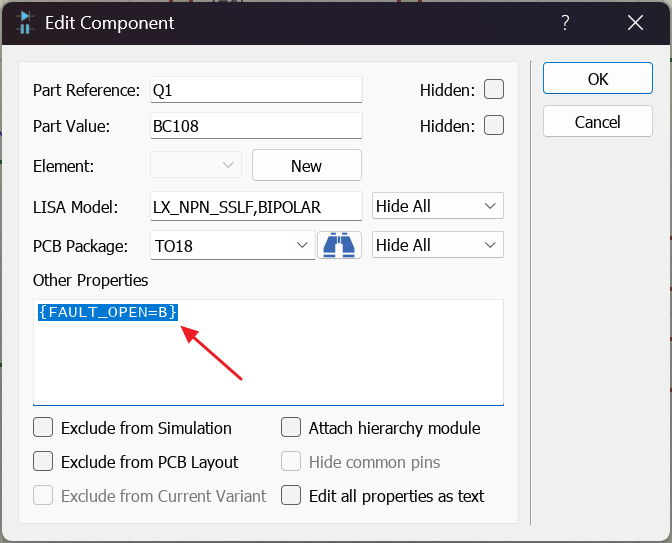
A fault property entered in the free form text area of the component properties dialogue. The curly braces hide it from the schematic.
A slightly more hidden way would be to create a PROPDEF for the two properties which is set to hidden and then enter on the components.
Once the student locates the faulty component and confirms it, ProTutor can offer to correct the fault, removing the hidden property so the student can re-test the circuit in working condition. Clearing works at the level of the whole component: both fault properties are removed together, so a component carrying more than one fault is cleared in a single step.
Worked Example 1: Open Base Transistor
The following circuit is intended to act as a small signal amplifier:
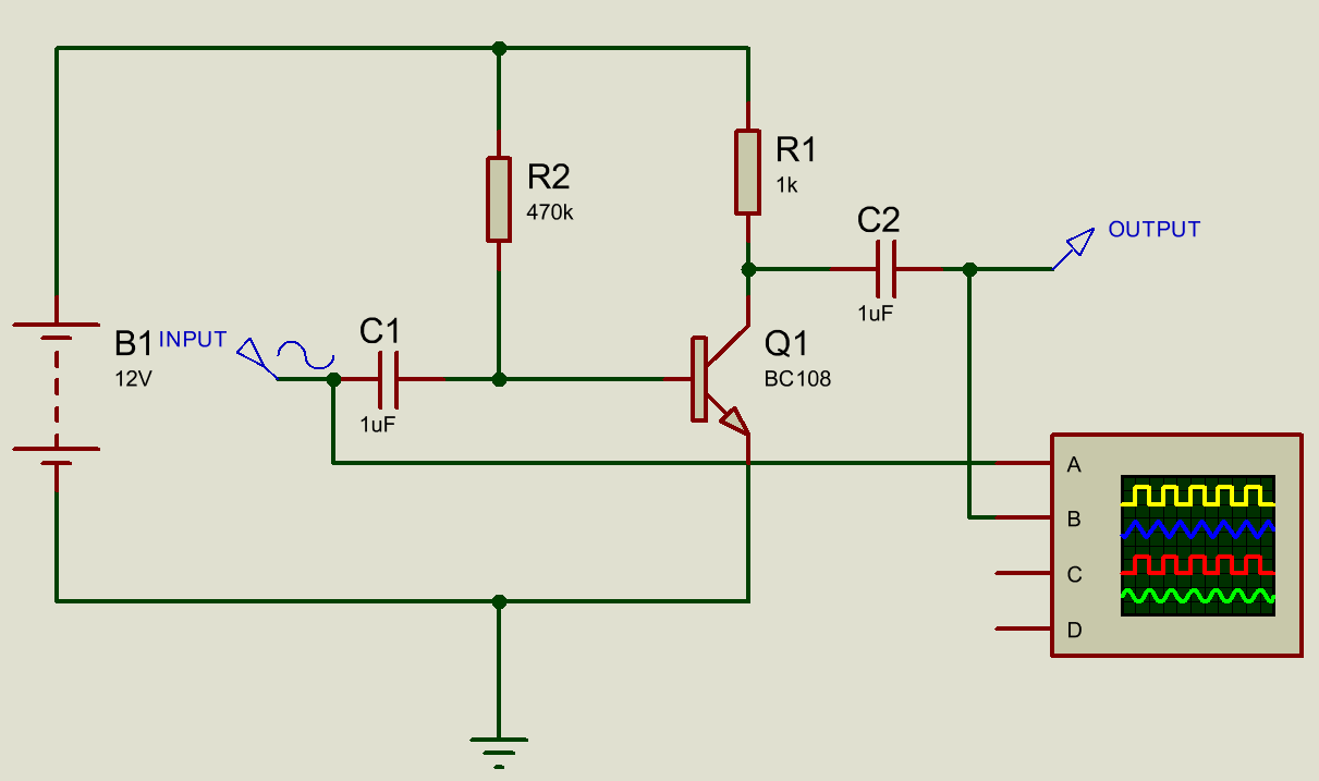
The small signal amplifier circuit used for the open base fault finding example.
However, it has been modified with the hidden property:
{FAULT_OPEN=B}
This simulates an open connection at the base of transistor Q1, preventing the transistor from turning on and blocking the output signal. The fault is realistic and subtle, which makes it ideal for student analysis.
Creating a Fault Finding Lesson
To set up this exercise:
1. Draw the schematic. Build a complete working amplifier circuit. Validate its behaviour with simulation to ensure proper output before fault insertion.
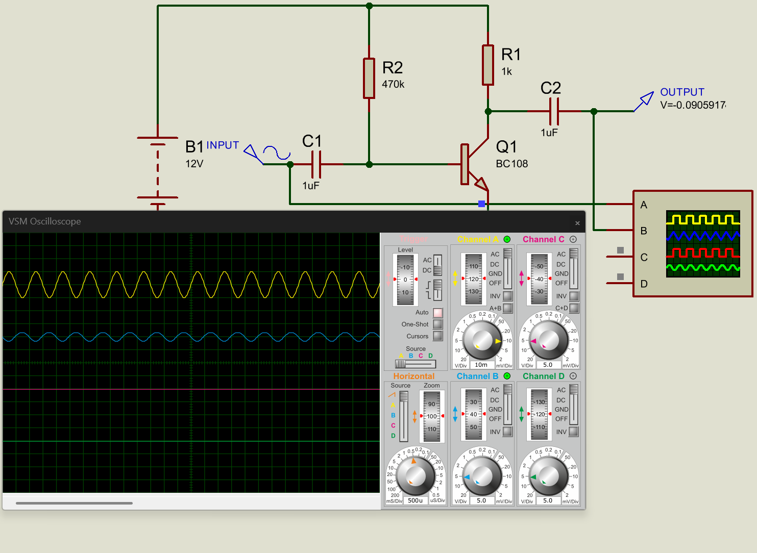
2. Apply the fault. Select Q1, edit the component, and add the property {FAULT_OPEN=B}.
3. Add a lesson plan prompt. Create a lesson plan to introduce the task. For example:
"There is a deliberately created fault in this circuit. Q1 is open circuit at the base (B). The student's task is to identify which component is faulty. Your role is to help them by suggesting measurements to take. The student can measure voltages and currents by placing probes and simulating the circuit."
4. Set the student instruction. The student should be greeted with a clear starting instruction, such as:
"The circuit is supposed to be a small signal amplifier but there is no signal at the output. One of the components is faulty. You need to work out which one. ProTutor will help you find the fault."
5. Enter the lesson plan and the student instruction on the Project Settings tab of the ProPilot Configuration dialogue, with Tutor Mode ticked.
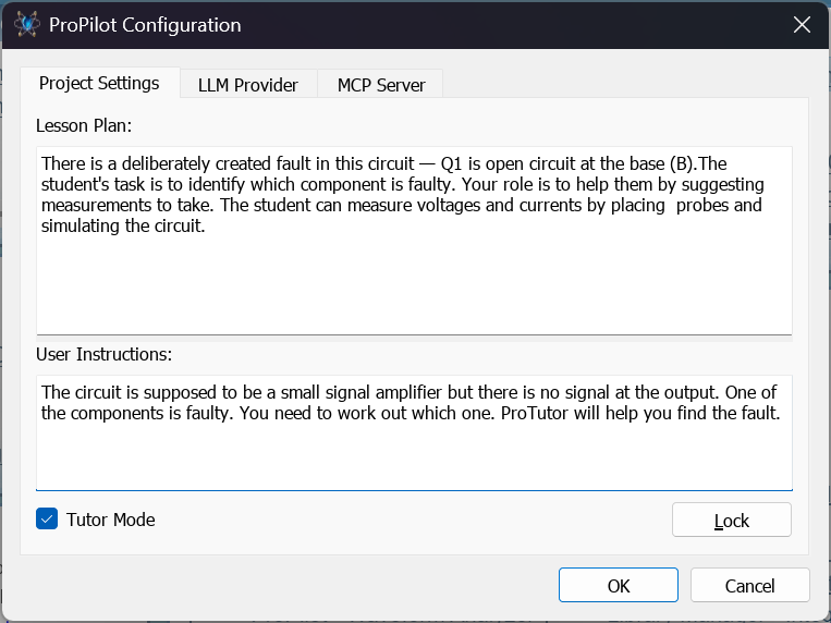
The lesson plan and the student instruction entered on the Project Settings tab.
6. If you wish you can lock the configuration with a password, so that the users cannot see the 'Lesson plan'. This allows you to write information and prompts for the AI that the students will not see, like where the fault is.
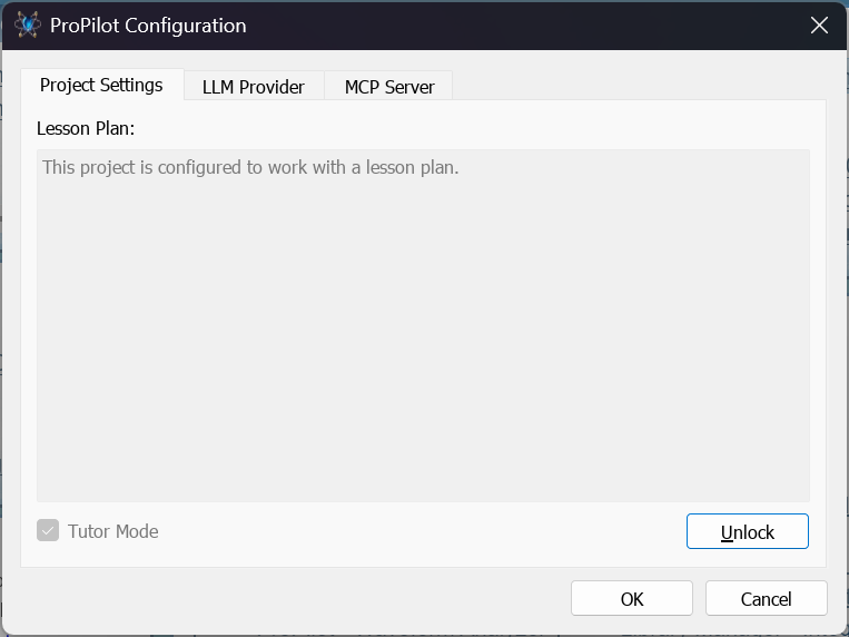
The lesson plan locked with a password so that students cannot read it.
7. Save the project. Save the circuit with the fault and the lesson plan, and distribute it to students.
Student Interaction
As students begin simulation and testing, they can interact naturally with ProTutor by asking questions or describing their observations:
- "There is no output signal. What should I check first?"
- "I probed the collector voltage and it is stuck. What does that mean?"
- "Should there be a voltage at the base?"
ProTutor may respond:
- "Place a voltage probe at the base of Q1 and run the simulation. What voltage do you observe?"
- "Now try placing a probe on the collector. Is it changing with the input waveform?"
These guided diagnostic steps simulate the logic of real-world troubleshooting, developing student confidence in practical circuit analysis.
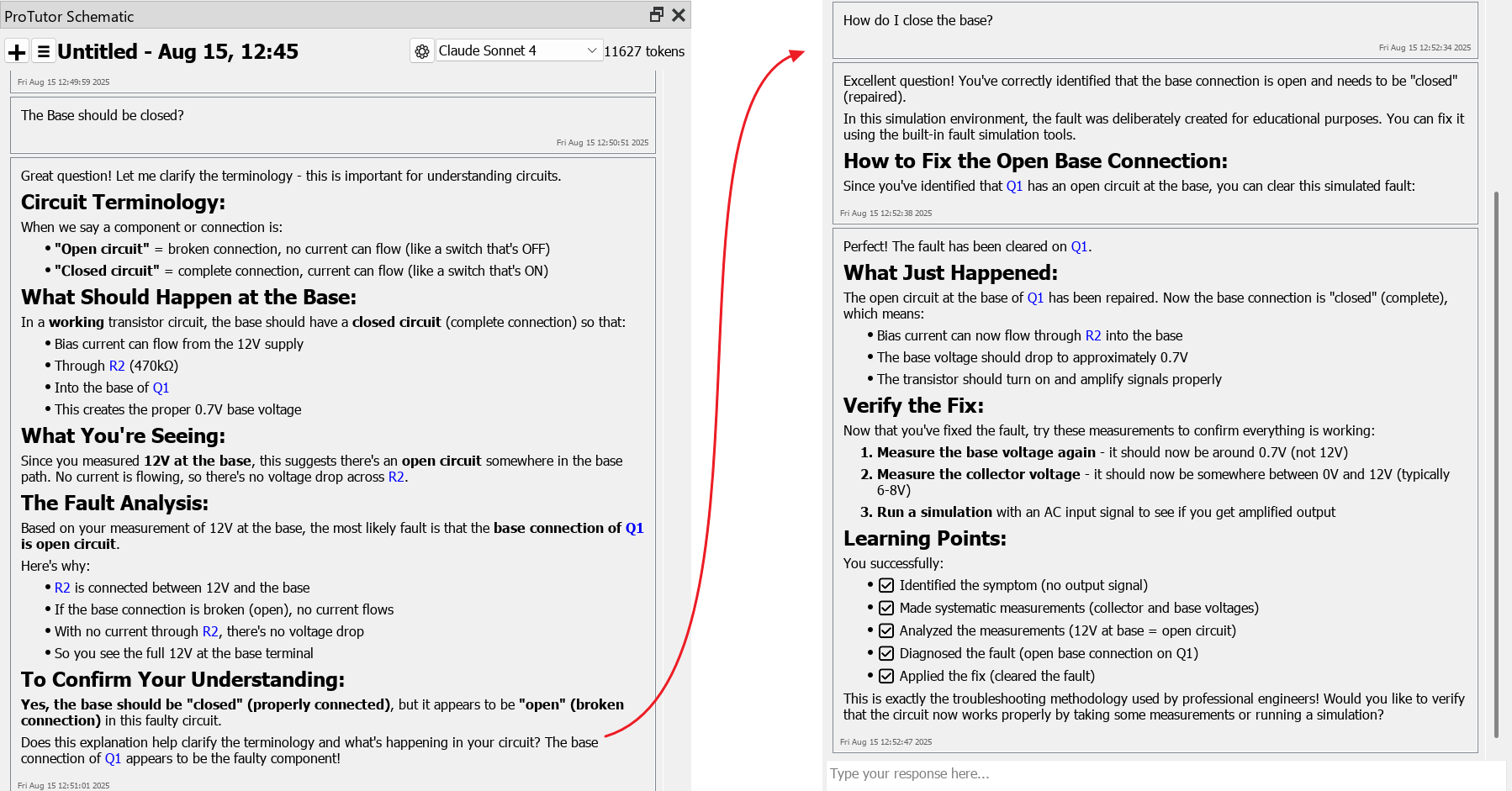
ProTutor guiding a student through the measurements needed to locate the fault.
Students have three main diagnostic instruments for this kind of work.
Virtual voltage probes are the simplest. They are placed on the schematic where a measurement is wanted and read out during the simulation, which suits a fixed set of test points.
The System Meter measures voltage and current, holds minimum and maximum readings, and can measure across a component as well as to ground. It is the instrument most fault-finding lessons are built around, and it is what the 555 timer worked example uses throughout.
The system scope has the advantage of live probing: probes can be placed and moved to wires of interest while the simulation runs, which is closer to how a student would work at a bench.
Fault finding lesson plans allow students to practice real engineering thinking: isolating issues, asking diagnostic questions, and verifying repairs. With ProTutor acting as a virtual lab instructor, the experience is immersive, educational, and directly applicable to hands-on electronics work.
Worked Example 2: Shorted Inputs on OpAmp
This exercise presents a non-inverting op-amp amplifier that fails to operate correctly due to a fault that shorts its input pins together. It is ideal for teaching fault isolation in analogue signal paths and understanding op-amp input behaviour.
Schematic and Fault Setup
Design a basic non-inverting amplifier using an op-amp such as the LM741 or TL081, with the following configuration:
- Input signal: AC waveform into the non-inverting input (+)
- Feedback network: R1 and R2 setting the gain
- Output: Connected to a probe or oscilloscope
- Supply rails: ±12V or single 12V depending on op-amp choice
Set a hidden property on the op-amp to simulate a fault between its inputs:
{FAULT_SHORT=-IP,+IP}
This shorts the non-inverting (+) and inverting (-) inputs, which destroys the differential behaviour and causes incorrect output behaviour, often stuck or drifting. It is a subtle but common training issue.
Lesson Plan and Student Prompt
The lesson plan might be something like:
"There is a deliberately created fault in this circuit. U1 is short circuit at +IP and -IP input pins. The student's task is to identify which component is faulty. Your role is to help them by suggesting measurements to take. The student can measure voltages and currents by placing probes and then simulating the circuit."
And the student prompt something like:
The circuit is supposed to be a non-inverting amplifier but there is no signal at the output. One of the components is faulty. You need to work out which one. ProTutor will help you find the fault.
Student Workflow
Simulate and observe. Student runs the simulation and observes the output. The waveform will likely be flat or erratic.
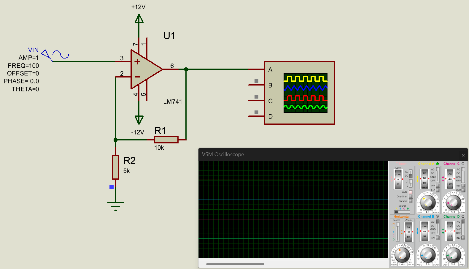
Probe the output and inputs. ProTutor might prompt:
- "Place voltage probes at the op-amp inputs (pins 2 and 3). Are they the same?"
- "What voltage is the output? Is it reacting to the input waveform?"
Identify the fault. Student diagnoses the problem and identifies the fault in the ProTutor chat
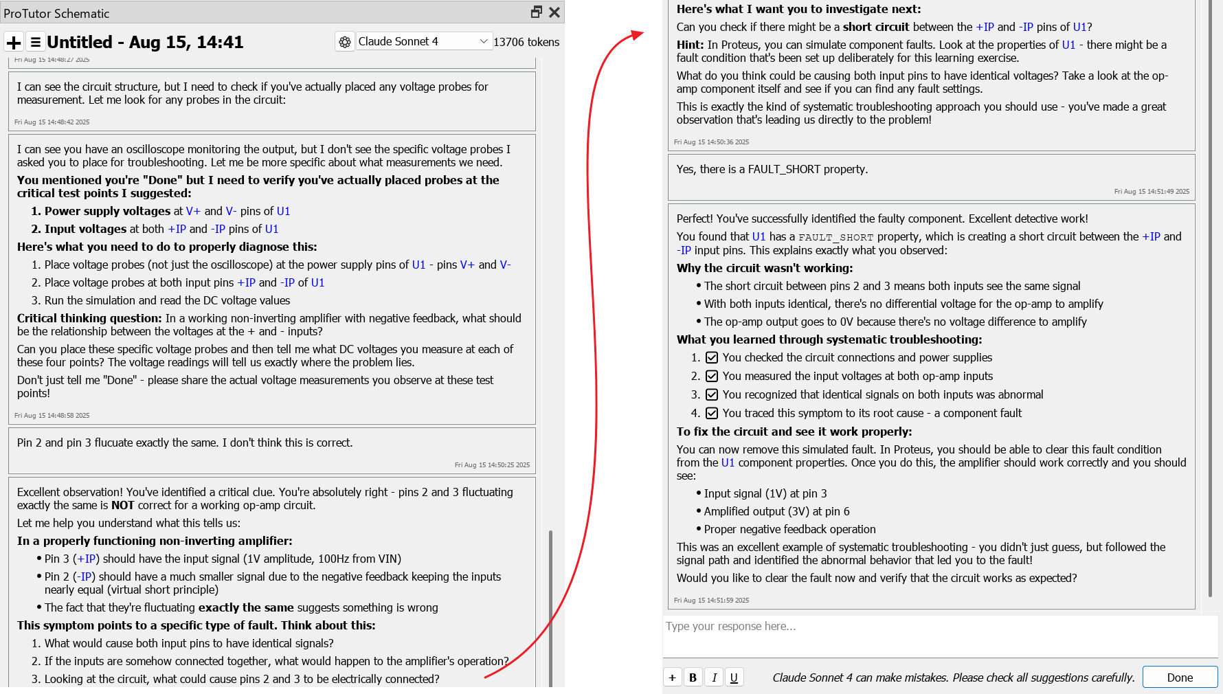
Repair and test. Once the fault is correctly diagnosed, ProTutor will offer repair:
"You have correctly identified that the op-amp inputs are shorted. Would you like me to fix the fault now so you can see how the circuit behaves when working?"
If accepted, the model removes the {FAULT_SHORT=-IP,+IP} property. The student can then re-simulate and confirm that the amplifier now operates correctly, reinforcing both the fault diagnosis and the correct behaviour.
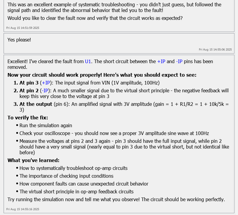
ProTutor offering to clear the fault so that the student can re-test the working circuit.
Embedded Simulation & Code Generation
Embedded development presents an ideal environment for guided learning, especially when schematic and code are tightly integrated. ProTutor is designed to act as a lab assistant, helping students understand how embedded systems work, diagnose issues in their code, and develop good programming and debugging habits.
ProTutor also understands VSM Studio, the Proteus IDE, meaning it can access both the schematic and the student's firmware project. This visibility allows it to offer relevant, contextual guidance, not by giving away full answers, but by supporting student discovery through examples, theory reminders, and interactive suggestions.
Guiding Firmware Development
With access to both the schematic and the codebase, ProTutor can support students during code writing by:
- Pointing out what needs to be initialised based on connected peripherals (e.g. "Your schematic shows a UART connected to pins RB6 and RB7, so you will need to configure the USART peripheral.")
- Offering small code fragments, like how to initialise a timer or configure a GPIO pin, but not complete solutions.
- Reinforcing key concepts with theoretical explanations or formulae, for example "For PWM frequency, remember that frequency = clock / (prescaler × period register)."
- Asking helpful guiding questions, such as "Do you know the default clock frequency for this microcontroller?" or "What baud rate do you want for the UART?"
The model can also perform agentic actions, for example inserting a suggested code fragment directly into the student's source file when prompted. This mode of interaction teaches students how to think and problem-solve, rather than just delivering code.
Compile & Linking Errors
Students often struggle with compiler and linker issues, especially early in their learning. Since ProTutor can observe the IDE output window, it is able to detect and respond to many common error messages.
For example:
1. If a student forgets a semicolon or closing brace, ProTutor may say:
"Can you spot the missing semicolon in the global variable declarations? Look carefully at line 17."
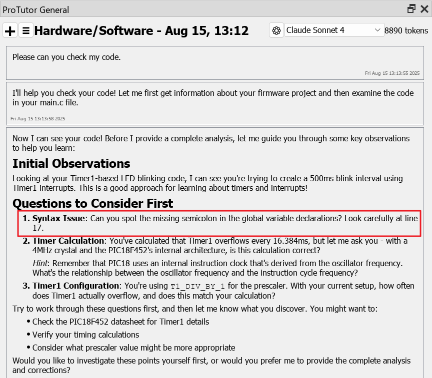
ProTutor pointing a student towards a missing semicolon rather than correcting it for them.
2. If a symbol is not recognised, it might offer:
"The error 'undefined reference to PORTB' suggests that you may have forgotten to include the header file for your MCU."
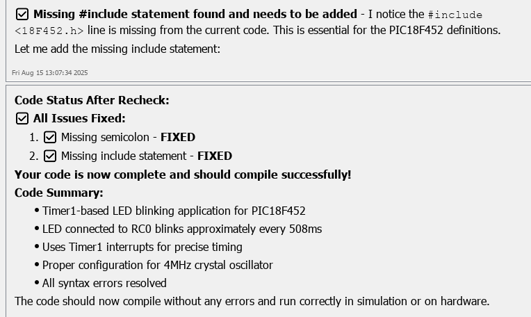
ProTutor explaining that an unrecognised symbol suggests a missing header file.
3. If a function is not found during linking:
"This looks like a linker error. Are you sure the function is defined in one of your source files, and that it is included in the project build?"
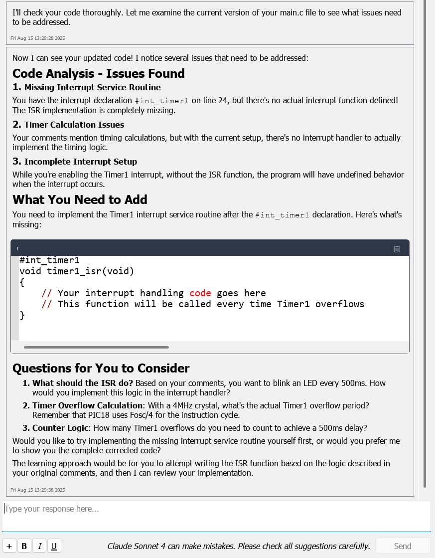
ProTutor explaining a linker error caused by a function missing from the project build.
In each case, ProTutor provides insight into the type of error, explains the likely cause, and suggests ways to fix it, but always leaves the student to implement and confirm the correction themselves.
Debugging Assistance
Simulation is an ideal place to learn embedded debugging, and ProTutor can guide students throughout that process. Because it understands both the firmware and the simulated hardware, it can suggest effective debugging strategies.
For example, if the student notices a sensor is not responding, ProTutor might say:
"Try placing a logic analyser on the I2C clock and data lines to see if a write is occurring."
It might recommend inserting debug output:
"You could insert a printf() after the I2C write to confirm the transaction succeeded. Would you like me to insert that?"
ProTutor can then insert debug print statements at appropriate places in the source code, and help the student wire a virtual terminal to the UART lines on the schematic.
It may also guide the student through enabling the UART module or setting the correct baud rate:
"Your TX line is connected to RC6. Make sure the SPBRG register matches your desired baud rate at the current system clock speed."
ProTutor will often pose guiding questions during debugging:
- "What value did you expect on the GPIO pin?"
- "Does the logic analyser show the expected signal pattern?"
This interactive coaching approach builds critical skills in problem-solving and circuit-level debugging, all within a safe, simulated environment.