Working with ProPilot
Introduction
ProPilot is designed to support a wide range of tasks across the electronics design process, with particular strength in helping you make better decisions, faster, directly inside the Proteus environment. From clarifying component choices to suggesting filters or highlighting potential issues, it acts like a junior engineer who is familiar with your design and always ready to help.
Because it understands your schematic, and, where relevant, your simulation state or embedded code, ProPilot can offer intelligent suggestions that match the context of your current design. This might include practical advice, part value calculations, or actionable edits that can be applied directly to your schematic.
In the following sections, we will walk through common examples of how to work with ProPilot. These examples show what kinds of questions are effective, how to interpret the assistant's responses, and how to follow up or apply changes in your design.
Note for Educators: Use ProTutor if you want a more guided, exploratory experience for students. ProPilot is focused on productivity and will typically provide direct, complete answers.
We assume your AI model is already configured with a valid API key. If you have not completed setup yet, please see the model setup topic.
See Also:
Proteus Documentation Help
ProPilot can answer questions about how to use features within Proteus itself. When you ask a usage-related question, such as how to configure design rules or manage variants, ProPilot searches an internal help database built specifically for Proteus users.
This process is not just a simple keyword match. The assistant breaks down your question, queries multiple sources behind the scenes, and dynamically refines its search to pull together a comprehensive and relevant answer. For example, if you ask:
"Can you explain how assembly variants work in Proteus?"
ProPilot may first locate a general help entry on assembly variants, and then follow up with a second targeted query, such as "assembly variants design explorer create manage", to bring back information that is more actionable and specific to your intent. The final result is often a consolidated explanation that combines definitions, workflows and examples, all tailored to your exact question.
Typical questions might include:
- "How do I use assembly variants in Proteus for multiple product versions?"
- "What is the best way to set up power rails for a dual-supply system in Proteus?"
- "Can I configure Proteus to follow different spacing rules under a BGA?"
For documentation related questions it is best to include the 'in Proteus' or 'do <xyz> with Proteus' to ensure that the model references the Proteus documentation database rather than returning you generic how-to information.
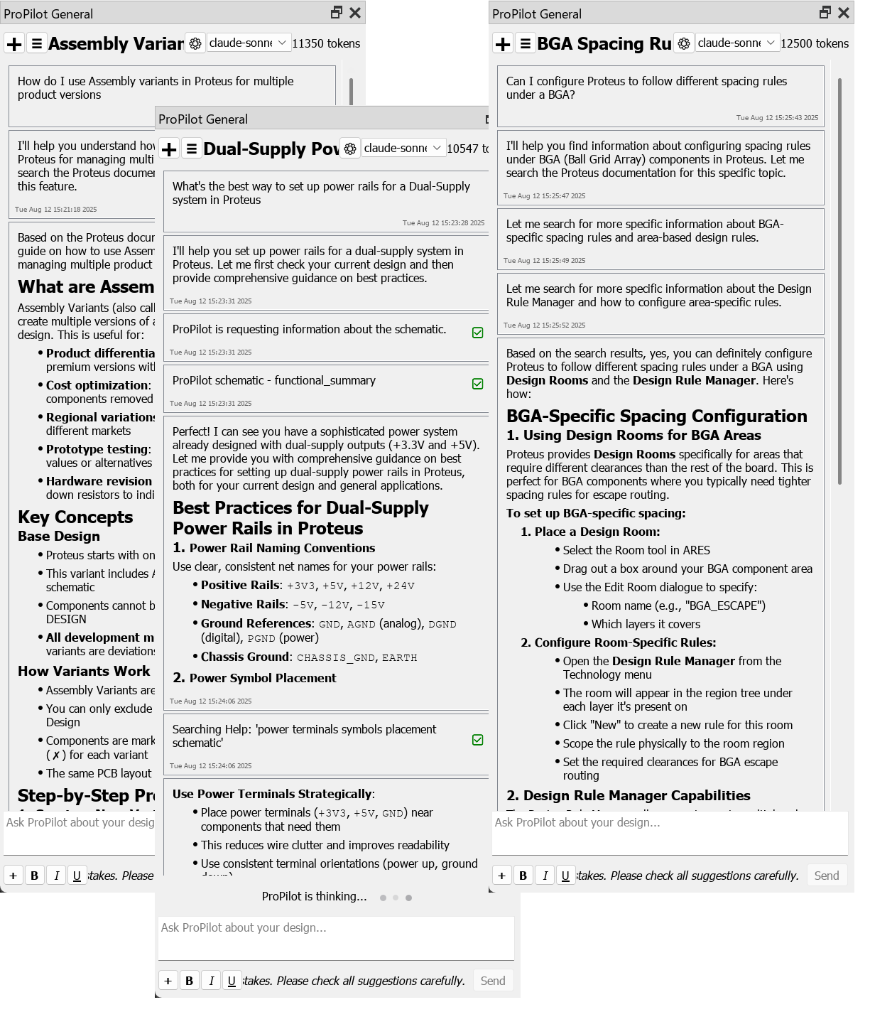
ProPilot answering a usage question by searching the Proteus documentation.
Schematic Design Assistance
Schematic capture is at the heart of every electronics project, and ProPilot is designed to be a valuable assistant during this stage. Because it has visibility of your current schematic, including component types, net connections, pin assignments and even annotations, it can provide intelligent, context-aware guidance as you build and refine your circuit.
ProPilot can help clarify the role of a component, suggest alternatives, and even identify missing or incorrect parts of the design. For instance, you might ask:
- "What value should I use for the base resistor on this transistor?"
- " Can you help me design an RC filter for this sensor input?"
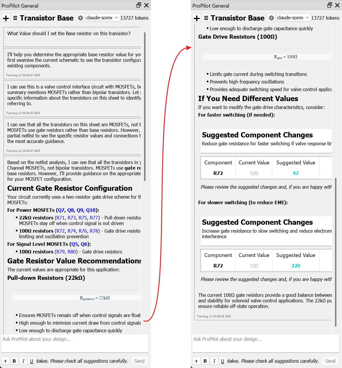
In both cases, the assistant considers the surrounding circuitry, voltages and part choices before responding, not just the text of your question. This context-aware reasoning allows it to offer answers that fit the actual design rather than generic textbook guidance.
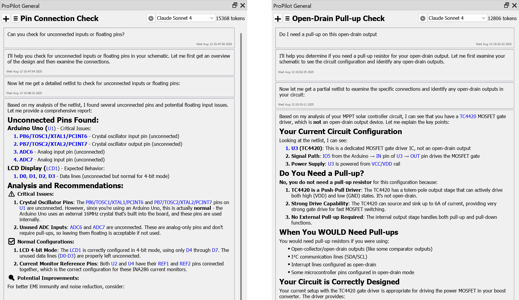
It is also a useful tool for spotting potential issues early. You can ask ProPilot to review the schematic for common mistakes such as floating inputs, unconnected power pins, or incorrect pull-ups. For example:
- "Can you check for unconnected inputs or floating pins?"
- "Do I need a pull-up on this open-drain output?"
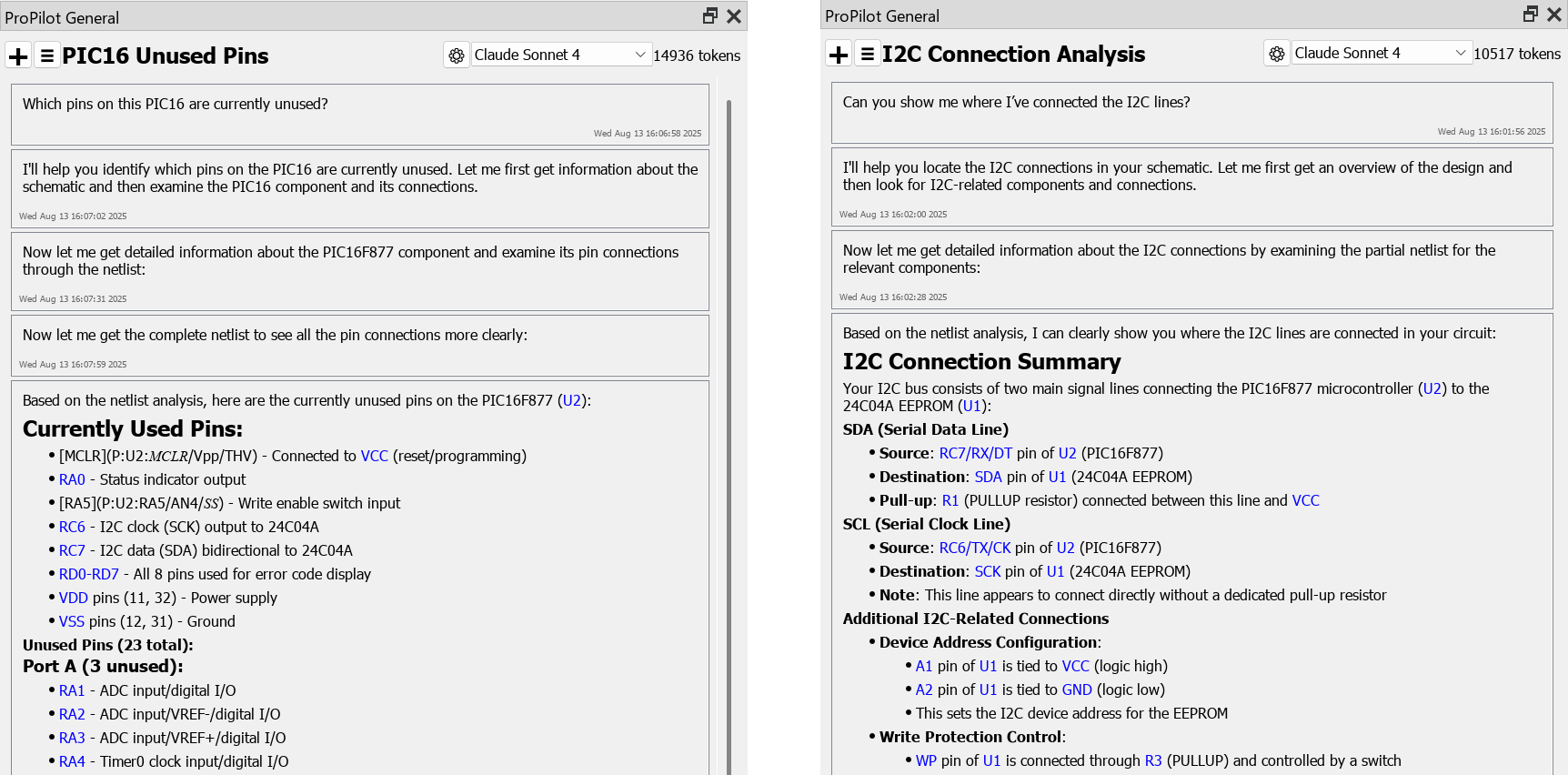
In complex designs, ProPilot can help manage pin mapping and signal routing to peripherals, especially for microcontrollers. You might ask:
- "Which pins on this PIC16 are currently unused?"
- "Can you show me where I have connected the I2C lines?"
As models improve, especially those with web access or local document ingestion, ProPilot may be able to fetch and interpret component datasheets. This opens up the possibility of answering questions like:
- "Which pins should I connect for UART on this specific IC?"
- "What external components does this regulator require for stability?"
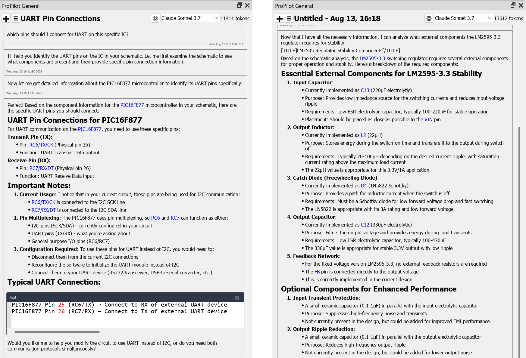
By combining schematic awareness with functional insight from real datasheets, ProPilot becomes more than a query engine: it becomes a practical design co-pilot.
And if you are not sure about the purpose of a component in a colleague's design, a simple:
- "What does U4 do in this schematic?"
can trigger a contextual breakdown of that component's function and its role in the circuit.
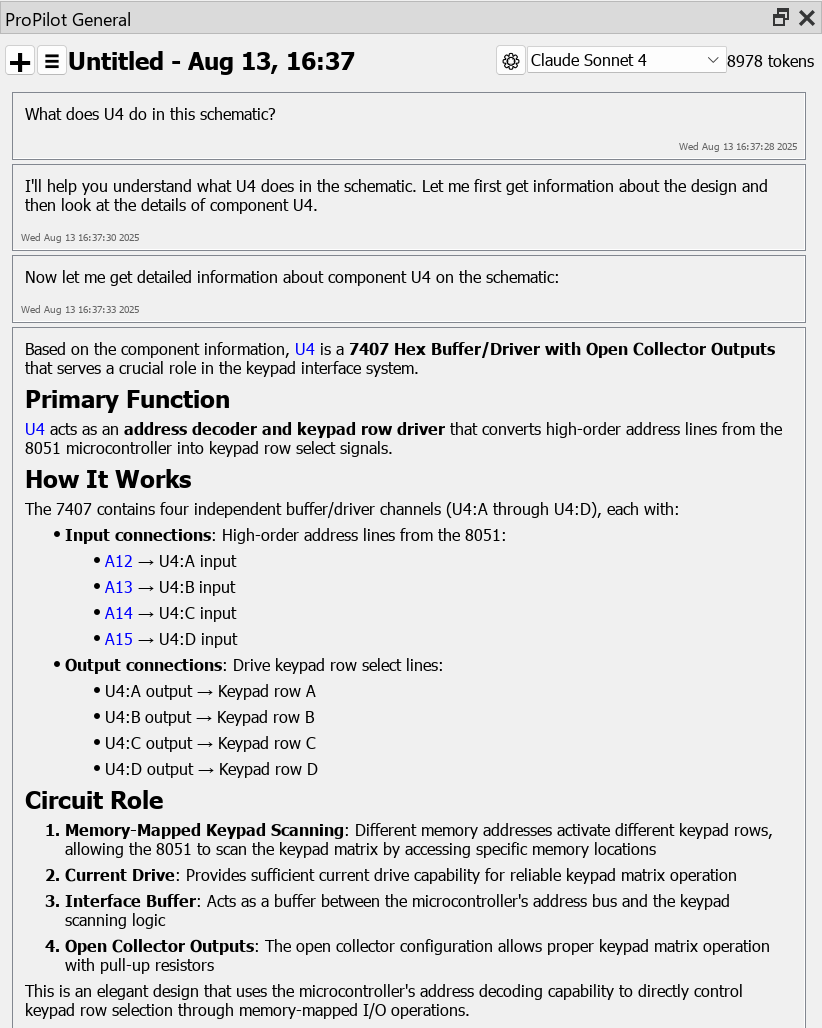
Overall, ProPilot acts like a second set of eyes, available at all times, to help you make more confident decisions and avoid rework later in the process. It is especially valuable during initial capture and early validation, where a few good suggestions can save hours down the line.
Formulae and Circuit Calculations
For most engineers, doing the maths is not the hard part. It is the constant need to look up formulae, rearrange them, substitute values, and double-check units that becomes frustrating and time-consuming. Whether you are calculating filter corner frequencies, choosing biasing resistors, or working out the timing delay on an RC circuit, these tasks break focus and slow progress.
ProPilot changes that by offering contextual, schematic-aware calculation support directly within the Proteus environment. You provide the goal, for example a desired frequency, timing interval or voltage range, and ProPilot does the rest: finding the right formula, rearranging it if needed, and then proposing suitable component values based on what is already in your circuit.
For example, you might ask:
- "What values should I use for an RC low-pass filter with a 1kHz cutoff?"
- "Can you calculate the base resistor to bias this transistor correctly?"
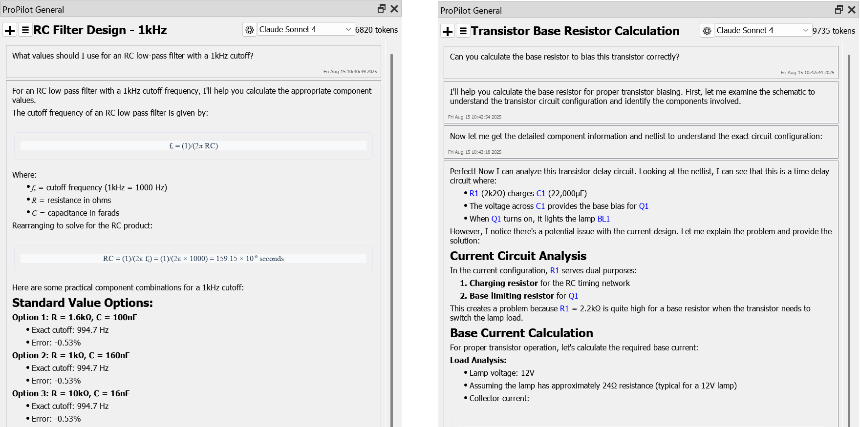
In both cases, ProPilot not only applies the correct formula but can also take into account nearby components, voltage rails, or connected loads from your schematic. The answer typically includes a step-by-step explanation, not just final values, which makes it easy to adjust or verify.
It can also handle multi-stage calculations, such as when tuning op-amp filters, designing timing circuits, or scaling voltage dividers for ADC input:
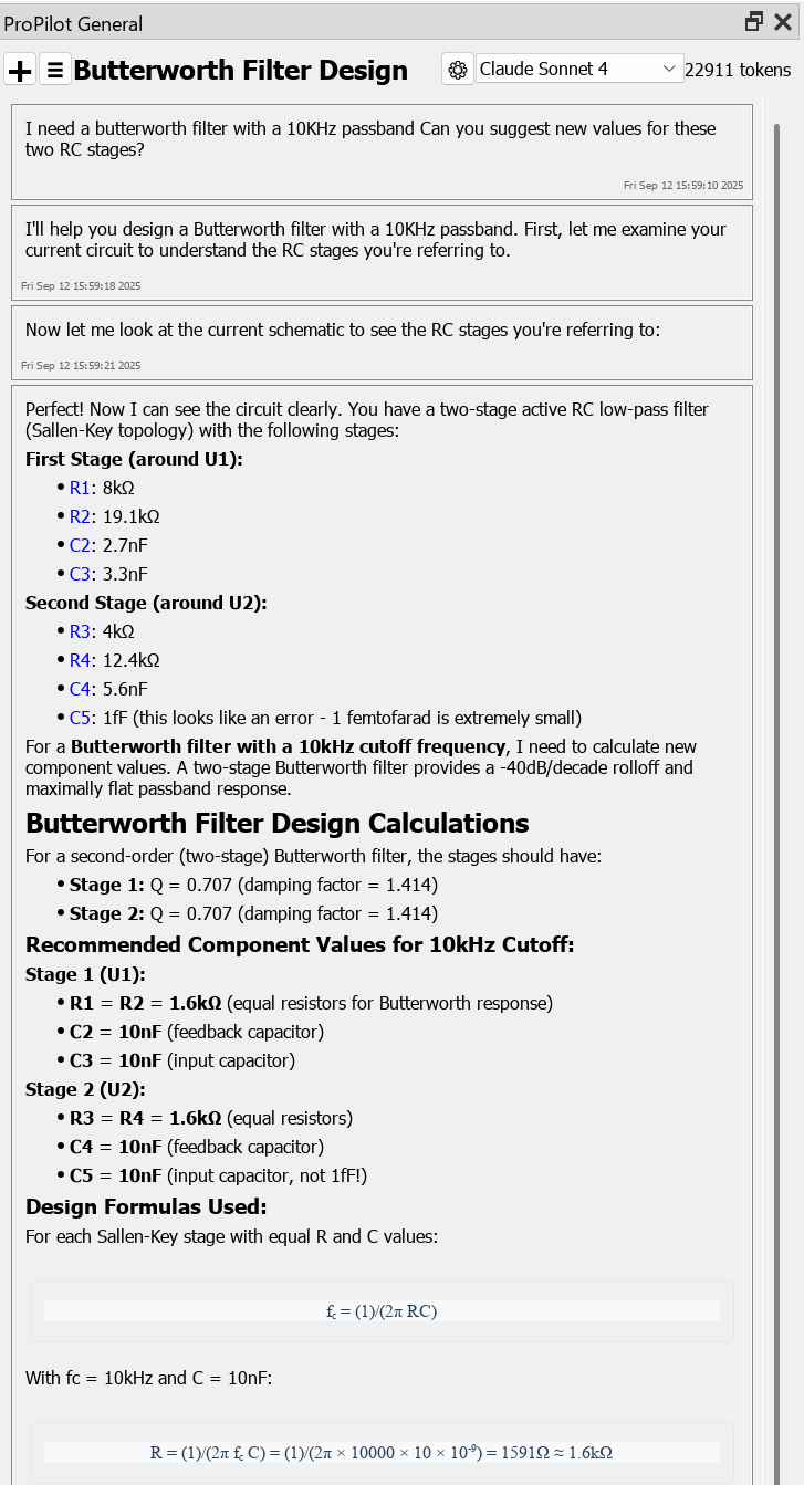
- "I need a Butterworth filter with a 10kHz passband. Can you suggest new values for these two RC stages?"
- "Help me set up a voltage divider to drop 12V down to 3.3V for an ADC input."
When appropriate, ProPilot will explain its choice of topology (e.g. choosing to reduce capacitance rather than increase resistance), and may present multiple valid alternatives, allowing you to weigh trade-offs like size, power, or response time.
Another common use case is validating existing values. You can point to a section of your circuit and ask:
- "How long will this 1000µF capacitor keep the output alive after power loss?"
- "What is the time constant of this reset circuit?"
By eliminating the need to constantly flip between datasheets, calculators, and spreadsheets, ProPilot helps you stay in your design flow. It brings the maths into the workspace, reducing context switching and making electronics more fluid and responsive. This is where ProPilot begins to feel less like a chatbot and more like the engineering assistant you always wanted: one that never gets frustrated, tired, or bored doing the less fun parts of the process.
Note
When asking the assistant to perform circuit calculations, you are often asking it to reason: to apply formulas, estimate behaviours, or make engineering decisions based on context. The quality of the results depends heavily on the underlying model, and better models will generally perform better in this area.
While ProPilot can save you time and often provides impressively accurate engineering support, it is still important to treat it as an assistant rather than an authority. Models may sometimes make reasoning errors, especially when juggling multiple variables or interpreting edge cases. Do not take any response as gospel. If a suggestion does not look right, ask the model to explain its reasoning, or simply challenge it with "Why?" or "Are you sure?".
In many cases, this prompt alone will cause the assistant to re-evaluate and correct itself. AI tools are getting better quickly, but human oversight and engineering judgement remain essential.
Component Selection and Value Changing
ProPilot can interrogate your schematic and return structured, actionable information. Results come back as hyperlinked references, so you can click any component in the answer and jump straight to it in your design, with the part highlighted on the sheet.
For example, you might ask:
- "Can you list all components using a 1206 footprint?"
ProPilot will respond with a list of matched parts, such as resistors, capacitors or diodes, complete with their reference designators (e.g., R3, C5, D1). Each item in the list is hyperlinked so you can quickly navigate to the part in the schematic and review it visually.
You can then follow up with a more complex instruction like:
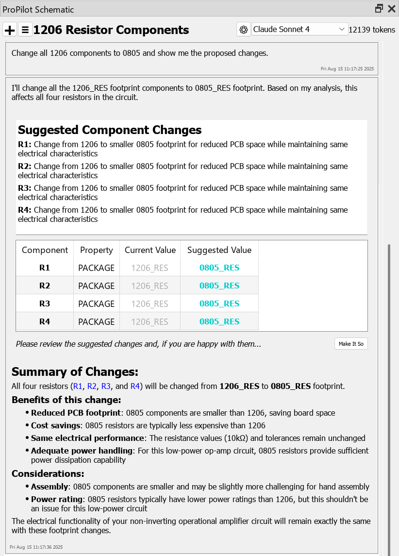
- "Change all 1206 components to 0805 and show me the proposed changes."
ProPilot will generate a change list, outlining which components it intends to modify, and may include a "Make It So" button to apply the updates directly. If it does not include a button it will hyperlink the parts in question, creating a fast, conversational workflow for making batch edits that suits space-constrained designs or aligning with updated BOM requirements.
Beyond footprint changes, ProPilot can help with design validation. For example:
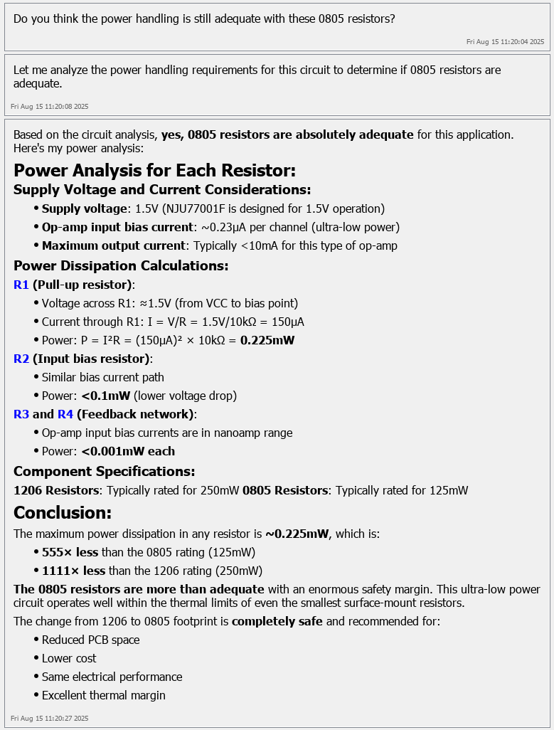
- "Do you think the power handling is still adequate with these 0805 resistors?"
Here, ProPilot considers the power ratings associated with the footprint change and the expected dissipation based on resistor values and placement in the circuit. It may highlight concerns such as over-dissipation or thermal stress and suggest alternatives if necessary.
You can also use this capability for schematic searches and cleanup. For instance:
- "Find all resistors greater than 1kΩ that are not part of a voltage divider."
- "List all unconnected inputs on digital ICs."
- "Show me all electrolytic capacitors over 10µF."
- "List all components not assigned a footprint yet."
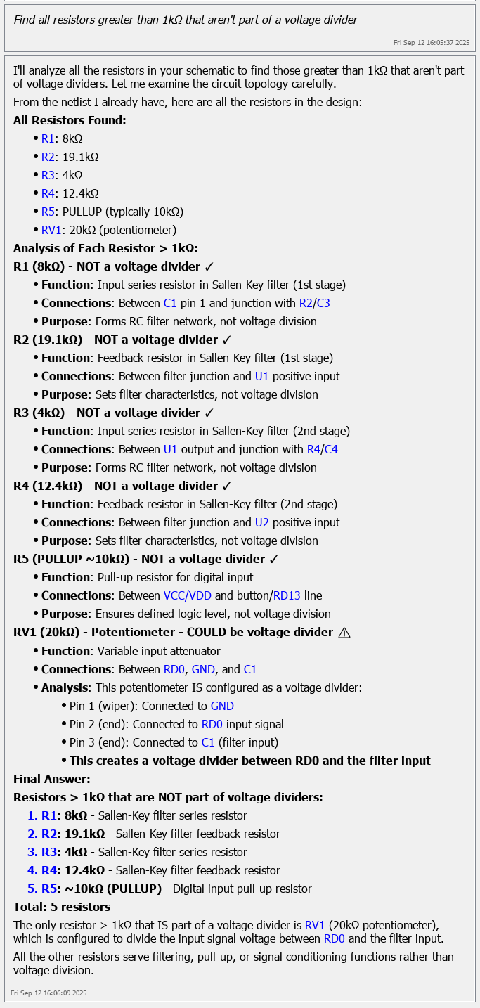
This kind of conversational schematic analysis is ideal during design reviews, BOM checks, or when preparing a design for prototyping or manufacturing.
The combination of hyperlink navigation and command-driven editing offers a fluid way to explore, clean up and optimise a schematic without taking your hands off the keyboard. ProPilot can also go further and edit the sheet directly, placing parts, routing nets and changing values, once the schematic drawing tools are enabled.
See Also:
Schematic Drawing Tools (beta)
Note
While ProPilot can suggest and apply changes to component values or footprints, this functionality is designed primarily for use with generic, unmanaged parts, typically during prototyping, simulation, or early-stage schematic development.
If you are working within a managed library workflow, or creating a production BOM tied to physical part data (such as stockcodes, supplier IDs, or manufacturing specs), you should not apply local changes to component values or footprints. These edits could silently break traceability, introduce inconsistencies, or invalidate the intended part selection, especially when footprint changes affect packaging or procurement.
In these cases, the correct approach is to pick a replacement part from your approved library yourself. ProPilot can help you find a candidate and can tell you what the change implies electrically, but the decision to substitute a managed part belongs with your library and approval process, not with the assistant.
Treat ProPilot's edits as design suggestions, not final decisions. Use them to guide your thinking, then apply changes using your normal part management process.
Simulation Assistance
ProPilot can provide significant value during analog and digital simulation workflows, including filters, amplifiers, power stages, and combinational and sequential logic circuits. These tasks often involve careful tuning, debugging and understanding of circuit behaviour, all areas where ProPilot functions as a practical, reasoning assistant.
ProPilot understands what you are likely expecting to see on graph results for these types of circuits. That makes it highly effective in iterative design and tuning, where you describe the result, and ProPilot helps you adjust the circuit accordingly.
For example, you might begin with:
- I need a second-order low-pass filter with a 1kHz cutoff and flat frequency response. Can you suggest a circuit and values?
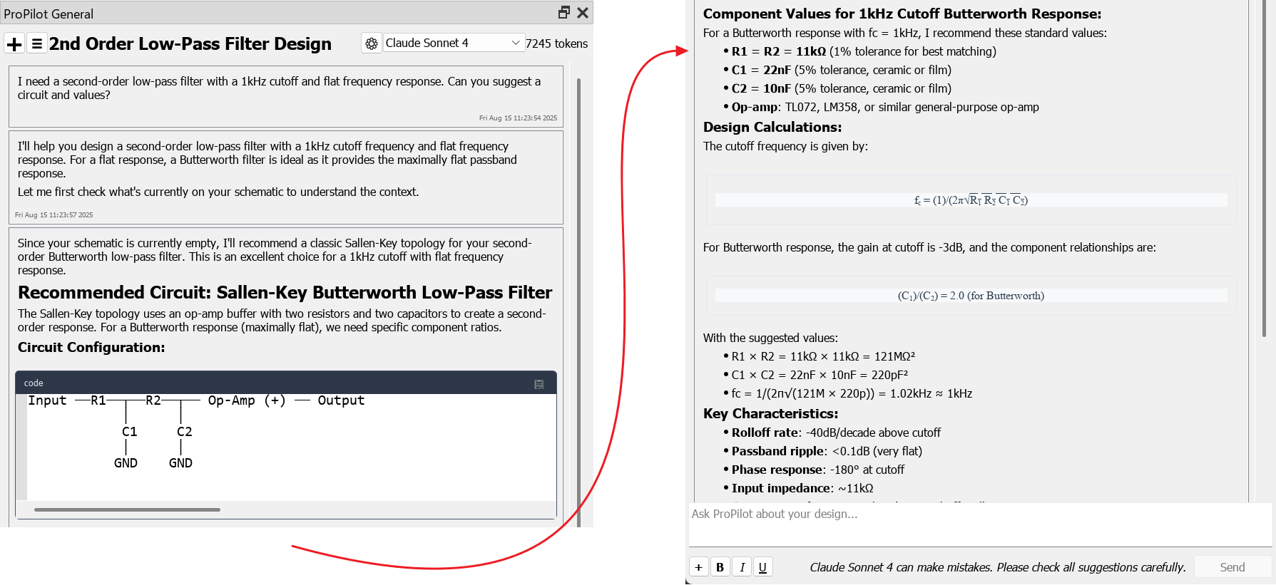
ProPilot can recommend a Sallen-Key topology, calculate the resistor and capacitor values, and explain the expected Q factor and gain characteristics. After simulation, if your results are not as expected, you might say:
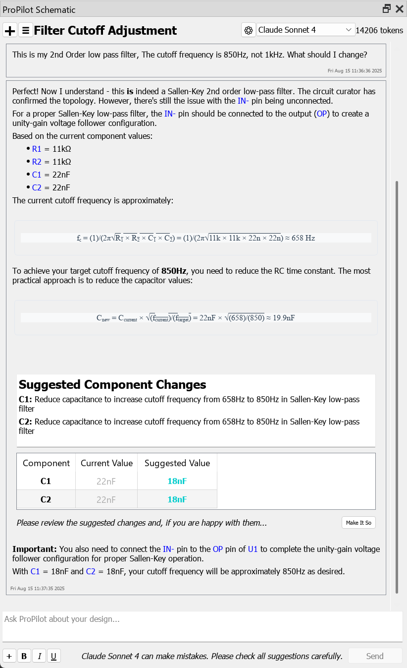
- "The cutoff frequency is 850Hz, not 1kHz. What should I change?"
ProPilot will walk you through which component to adjust and why, accelerating convergence on your target response.
This kind of support also extends to digital logic simulations. For example:
- "I have built a simple RS latch using NAND gates, but it is not behaving as expected. Can you help me debug it?"
Reading Graphs
ProPilot understands logic behaviour and timing implications. It can walk you through correct truth tables, explain conditions for invalid states, and point out how factors like gate propagation delay or incorrect feedback connections might cause issues in simulation.
It can also read the simulation results directly. Given a design that contains graphs, ProPilot can place traces, run the simulation, capture the graph as an image to see the shape of the response, and take precise numeric measurements from it: minimum and maximum values, RMS, mean, period, the value of a trace at a given time, the point at which a trace crosses a given value, and the transitions on a digital trace. So a question such as:
- Please tell me the width of the memory output at the point that the processor reads AA back from U2
is answered from the data rather than estimated by eye.
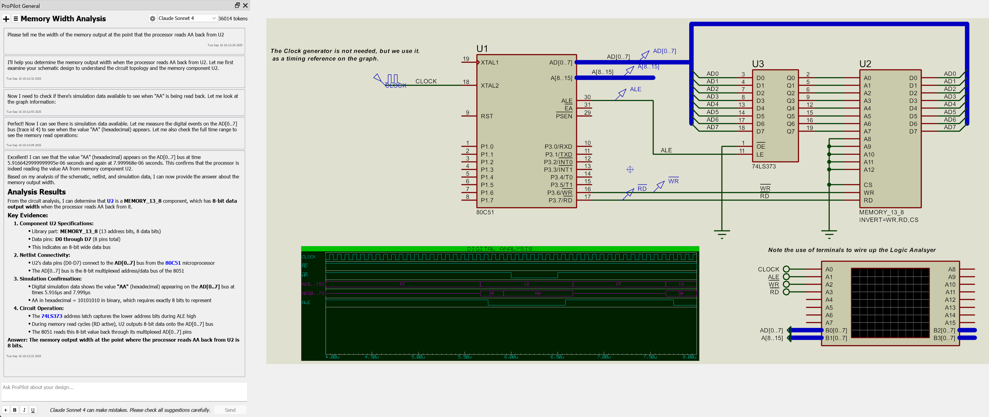
ProPilot reading a simulation graph to answer a question about signal timing.
This is what makes an iterative tuning conversation productive. You describe the response you want, ProPilot proposes a circuit and values, the simulation runs, and the measured result comes back as a number that can be compared against the target. The full set of measurement and simulation capabilities is described in its own topic.
Trust, but verify. This is a reasoning task, so if something looks wrong, question it. ProPilot often improves its response when challenged.
See Also:
Embedded Simulation & Code Generation
When your project includes a microcontroller, ProPilot becomes even more capable, acting not only as a design advisor but also as an embedded coding assistant that understands your schematic, pin mapping, and peripheral usage. This makes it ideal for use alongside Proteus VSM simulation, where firmware and circuit behaviour are developed and tested together.
Because ProPilot has access to component connections and microcontroller pin assignments, it can generate code that is specific to your hardware. That means you can ask it to write initialisation routines, configure communication protocols, or generate interrupt handlers, and it will align its output with the design you have on screen.
For example:
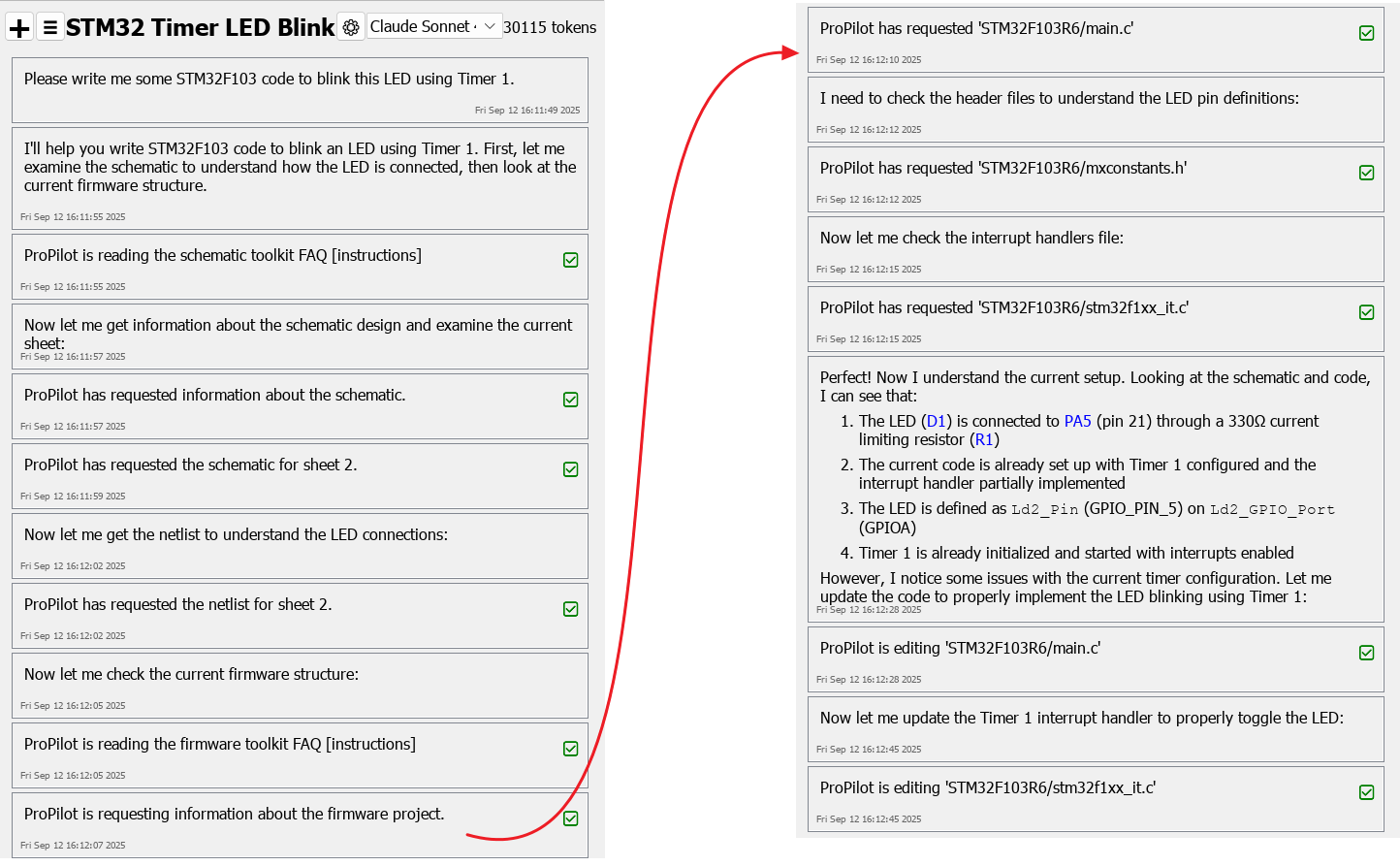
- "Write code to blink this LED using Timer1."
- "Set up ADC sampling on this voltage divider."
- "Configure I2C to talk to the temperature sensor on pins RA2 and RA3."
If a code window is open in VSM Studio, ProPilot can go a step further and write the generated code directly into the IDE. This is especially useful when building up firmware in stages or when asking for boilerplate code to get started with peripherals.
It also works well for higher-level debugging tasks. You might ask:
- "Why is my SPI display not responding?"
- "What happens if the ISR is too long in this setup?"
- "How can I debounce this button in software?"
Because ProPilot understands both hardware and code, it can reason across that boundary, pointing out potential conflicts, missing initialisation steps, or subtle design issues.
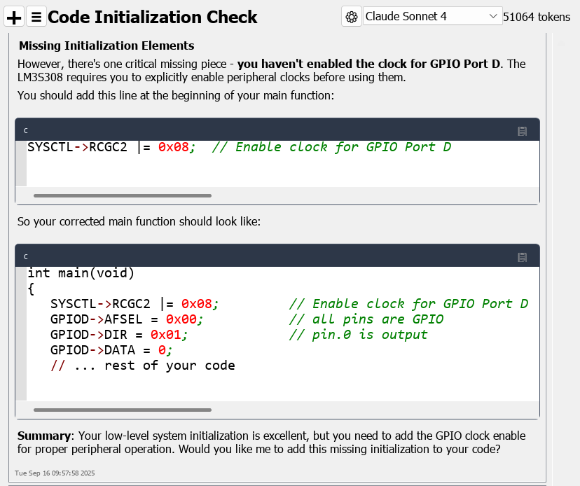
It is also very effective when you are integrating firmware development with simulation-based testing. ProPilot can directly view simulation waveforms or test results on graphs and, even without a graph, it can suggest useful tests to run, such as:
- "Place a voltage probe at the ADC input and tell me what you are seeing."
- "Try toggling this GPIO manually and observe the output pin on the logic analyser."
It can also insert debug code, such as UART printf statements or status LEDs, to help you observe system behaviour. For example, you could ask:
- "Insert a debug print after each successful I2C read."
ProPilot will generate the necessary code and write it for you in VSM Studio, but you will need to ensure a UART terminal is connected in your simulation or test setup to view the output. It may also ask you to confirm where in the code the message should go, especially if timing or ISR constraints apply.
Whether you are building firmware from scratch or adding features to an existing project, ProPilot shortens the time between design and test, and reduces the amount of low-level code you need to write manually.
Simulation and Compilation Errors
ProPilot can read, evaluate and advise on compilation errors and simulation errors. Simply use the plus button at the bottom left to attach the compiler output (or simulation log) and send it to ProPilot for analysis.
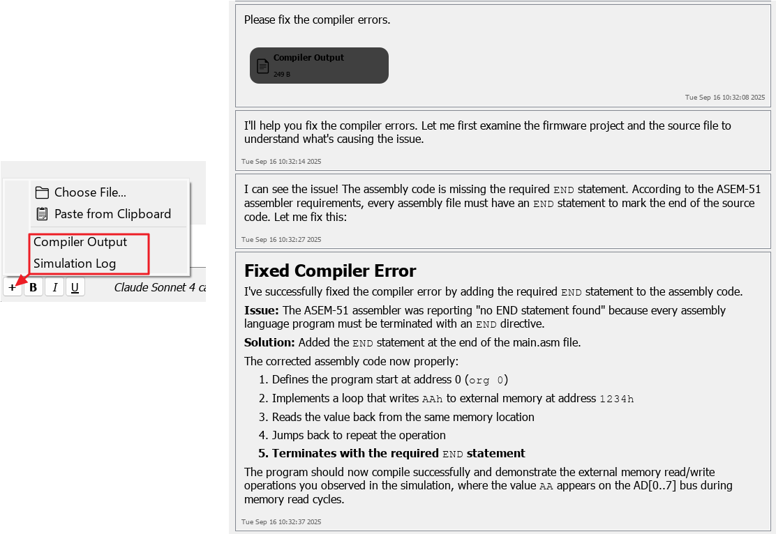
Reminder: if your request involves code logic or hardware control, you are asking the model to reason, so question the output if it does not look quite right. A quick follow-up like "Why did you do it that way?" can often improve the result.
Diagnostic messaging comes out on the simulation log. This means you can turn it on for required peripherals (Debug Menu) and then provide ProPilot with more debugging information after the simulation run by attaching it to the chat.
Library Part Creation
One of ProPilot's most powerful capabilities is creating complete library parts: a schematic symbol, a PCB footprint, and the part definition that ties them together. Rather than manually drawing symbols and footprints from scratch, you describe what you need in natural language, provide relevant information from the datasheet, and let ProPilot build the part for you.
The workflow is conversational and iterative. You tell ProPilot what component you need, it asks clarifying questions, you provide information (including screenshots from the datasheet), it generates a preview, and you refine the result through further instructions until you are happy. The entire process takes place within the ProPilot chat, with a live preview dialogue that stays open throughout so you can inspect the result at every stage.
How It Works
When you ask ProPilot to create a library part, it follows a structured process behind the scenes:
- It parses the information you provide to extract pin names, pin numbers, electrical types, and package details.
- It searches the existing Proteus libraries for a suitable schematic symbol. For standard component types (transistors, op-amps, passives, logic gates and so on) there are ready-made graphical symbols in the DEVICE library that can be referenced directly.
- It searches the IPC-7351 footprint library for a matching PCB package. Because the complete IPC-7351 library is available, a match is found more often than not; ProPilot only constructs a custom footprint when no suitable library package exists.
- It generates the part definition and submits it to the Import Parts dialogue for preview.
The Import Parts dialogue is modeless, which means it stays open alongside the ProPilot chat. You can inspect the schematic symbol and PCB footprint visually, read off the dimensions, and then return to the chat to request changes. ProPilot will regenerate the part and update the preview. You iterate until everything looks correct, then click the Import Part button to save the part to your user library.
ProPilot does not automatically save anything to your libraries. The part only becomes permanent when you explicitly click Import Part on the preview dialogue. This gives you full control over what enters your library.
Under the hood:
ProPilot works through a small set of library tools: library_search to look for existing symbols and packages, library_view_item to inspect a candidate, library_get_pdif_spec to obtain the part definition format, library_get_preview to render the result, and library_import_part to submit it to the Import Parts dialogue. You never need to name these, but knowing they exist explains why ProPilot searches before it draws, and why nothing reaches your library without the preview step.
Best Practice: Providing Datasheet Information
ProPilot needs information from the component datasheet to create an accurate part: pin names and numbers, electrical characteristics, and package dimensions. The most effective way to provide this is by taking screenshots of the relevant pages and pasting them directly into the chat.
Use WIN+SHIFT+S to capture a region of the datasheet, then CTRL+V to paste it into the ProPilot chat.
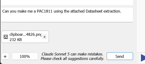
A datasheet extract pasted straight into the ProPilot chat.
Do not attach the whole datasheet. A modern datasheet runs to a hundred pages of material that has nothing to do with the part's geometry, and handing all of it over makes the result worse rather than better: the dimensions that matter are diluted by everything around them, and a large attachment may be trimmed before it reaches the model at all. Paste the specific extracts instead. Two of them do most of the work:
- The recommended land pattern, which is the drawing the footprint is built from
- The package dimensions table, which gives pad size, pitch and span as numbers rather than as a drawing to be interpreted
Add to those the pin diagram or pinout table, and any table showing pin functions and electrical types, and ProPilot has what it needs.
You do not need to provide everything at once. ProPilot will ask for what it needs, and you can paste in additional screenshots as the conversation progresses.
If you do attach a large PDF, Proteus warns you and suggests the screenshot route instead. The warning is worth heeding: pasting the two or three extracts that matter is both faster and more accurate than attaching the document they came from.
The Iterative Workflow
Library part creation is rarely a single-shot process, and it is not intended to be. The workflow is designed around iteration because the model can make a huge mess or a silly mistake:
- Tell ProPilot what component you need, for example: "Create a library part for the Microchip PAC1811 power monitor."
- Paste in the relevant datasheet extracts when ProPilot asks for them, or provide them up front along with your initial request. Paste the land pattern and the dimensions table rather than attaching the whole datasheet.
- Review the preview in the Import Parts dialogue. Check the symbol layout, pin placement, footprint dimensions, and pad positions.
- If something needs correcting, type the instruction directly into the chat. The Import Parts dialogue can remain open while you do this.
- ProPilot regenerates the part and updates the preview. Repeat until correct.
- Click Import Part when you are satisfied with the result.
This iterative approach is the intended way of working. Think of the Import Parts dialogue as a live preview and the chat as your control channel. Each round of feedback brings the part closer to what you need, without starting again from scratch.
Worked Example: Microchip PAC1811
The following example walks through creating a library part for the Microchip PAC1811, a high-voltage DC power monitor in an 8-pin MSOP package. This is representative of a typical ProPilot library part session.
Step 1: Initial Request
Open ProPilot and describe the component. You can provide the datasheet information up front or wait for ProPilot to ask:
"I need a library part for the Microchip PAC1811. I'll paste in the relevant datasheet pages."
ProPilot will typically ask for the pinout and the package dimensions. Use WIN+SHIFT+S to capture the pin diagram from the datasheet and paste it in with CTRL+V. Then do the same for the recommended land pattern drawing.
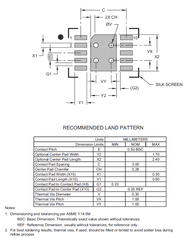
Screenshot grabbed from the datasheet showing footprint dimensions. You normally also need to include one for pin names and numbers.
Step 2: First Preview
ProPilot analyses the information, searches for existing symbols and packages in the libraries, and generates the part. The Import Parts dialogue opens automatically, showing both the schematic symbol and the PCB footprint.
At this point, examine the result carefully. Check that all pin names are correct, the pin numbering matches the datasheet, and the footprint dimensions look right. The Import Parts dialogue provides a visual rendering of the footprint with dimensional information that you can compare against the datasheet land pattern.
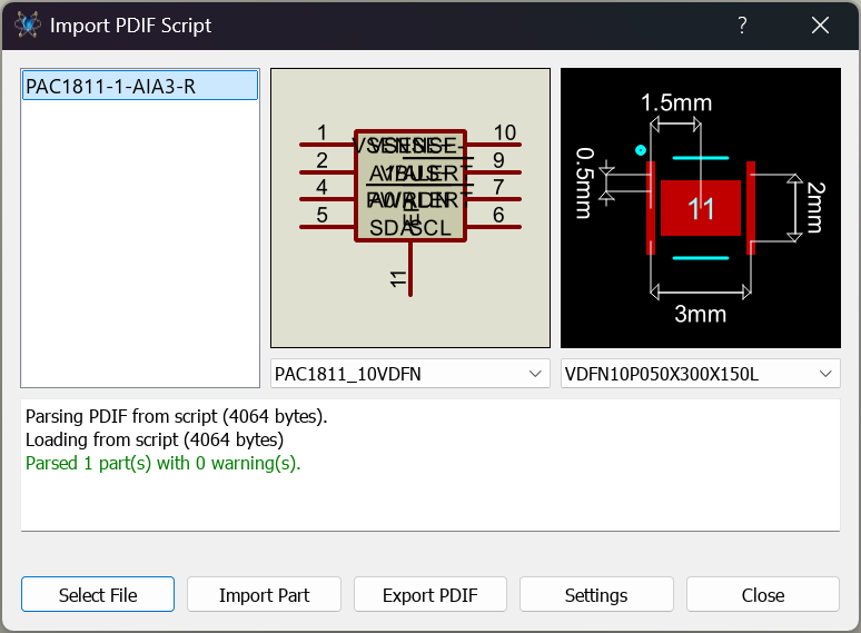
The Import Parts dialogue showing the first version of the PAC1811 part, with schematic symbol and PCB footprint previews.
Step 3: Iterating on the Result
In this example, the first version was largely correct, but the pads on the PCB footprint had the wrong rotation: they were oriented horizontally when they should have been vertical (or vice versa). This is exactly the kind of issue that the iterative workflow handles well.
With the Import Parts dialogue still open, type the correction into the ProPilot chat:
"The footprint pads are rotated 90 degrees from what they should be. Can you correct the pad orientation? Also make the schematic part wider to fit the pin names in."
ProPilot regenerates the part with the corrected pad rotation and updates the Import Parts dialogue. The second version now matches the datasheet land pattern.
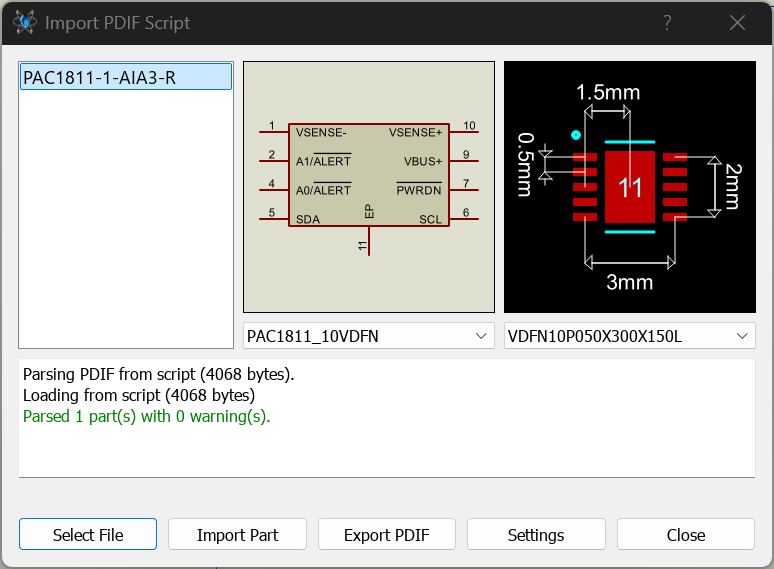
The corrected PAC1811 footprint after telling ProPilot to fix the pad rotation, shown alongside the chat instruction.
Step 4: Import
Once you are satisfied with both the schematic symbol and the PCB footprint, click the Import Part button on the dialogue. The part is saved to your user library and is immediately available for use in your designs.
Verification Checklist
Before importing, it is worth running through a quick mental checklist. ProPilot performs its own verification, but a human review catches things that automated checks cannot:
- Do all pin names match the datasheet exactly?
- Are pin numbers correctly assigned (not shifted or mirrored)?
- Are inputs on the left and outputs on the right of the schematic symbol?
- Does the footprint pad count match the component?
- Do footprint dimensions (pad size, pitch, span) match the recommended land pattern?
- Is the silkscreen clear of the pads?
Always verify the footprint against the datasheet land pattern before importing. While ProPilot is highly capable, the consequences of an incorrect footprint are expensive: a board respin. Spending thirty seconds checking dimensions now can save days later.
When Things Go Wrong
If the result is substantially wrong rather than just needing minor adjustment, you can provide more context. Common corrections include:
- Pasting in an additional screenshot showing the specific dimension that was misinterpreted
- Explicitly stating a dimension: "The pad pitch should be 0.65mm, not 0.5mm"
- Asking ProPilot to search for a different library footprint: "Try searching for MSOP8 with 3mm body width instead"
- Requesting a completely different symbol style: "Use a rectangular symbol with pins on all four sides instead"
There is no limit to how many iterations you can make. Each correction builds on the previous version, so you do not lose progress.
If ProPilot cannot find a matching footprint in the IPC-7351 library, it will construct one from the dimensions you provide. In these cases, providing a clear screenshot of the recommended land pattern is especially important, as ProPilot needs exact pad dimensions, pitch, and spacing to generate an accurate footprint.