THE AUTO-PLACER DIALOGUE
Overview
The auto-placer is highly configurable and as a result the dialogue form may at first appear somewhat daunting. However, it will operate quite happily with the default settings for most purposes. The function of the various fields is discussed below.
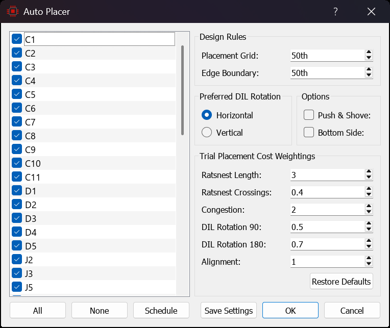
The Auto-placer dialogue form
The Component Selector
The left hand pane lists all of the components still to be placed. When the dialogue form is first displayed the components are listed in alphabetical order, with every component in the list ticked for placement. Clear the tick against any component you do not want the placer to touch.
The All and None buttons tick and clear every component in the list. The Schedule button requires a little more explanation. By default the components are presented in alphanumeric order, but pressing Schedule presents them in the order in which the auto-placer will place them. Components that are not ticked for placement always appear at the bottom of the list. Once you have pressed Schedule the button greys out until you change the tick state of a component.
Design Rules
The Placement Grid defines the step size used by the auto-placer when trying to find a position for each component. This should always be set to a multiple of the grid size you are going to use for auto-routing. Values other than 100th, 50th or 25th would be highly unusual; the default is 50th.
The Edge Boundary defines the minimum distance to be allowed between any component and the edge of the board as drawn on the Edge layer. The default is 50th.
The time to complete placement will change exponentially as you decrease the placement grid. If at all possible, try to keep the placement grid at 50th or higher.
Trial Placements and Cost Weightings
Auto-placement is achieved by trying the next component at various positions on the board in an attempt to minimise a number of key factors. You set the relative importance of these factors by entering a value for each of the six categories; the larger the number, the more important that factor becomes. A value of zero removes the factor from the costing altogether.
Ratsnest Length
Arguably the most important weighting factor in terms of routability, this assigns importance to the minimisation of the length of inter-connectivity of components before routing. Note however that in our experience this should be balanced with some knowledge of the number of ratsnest crossings. A board with short total ratsnest length and a large number of crossings can often be unroutable.
Ratsnest Crossings
This weighting defines the importance of minimising the number of ratsnest lines which cross. As a component is moved around the board the ratsnest length and number of crossing changes, both of these factors will affect the overall routability of the final placement. It is important to get a good balance between this and ratsnest length.
Congestion
Small components may be encouraged to avoid highly congested areas of the board by increasing the importance of the congestion weighting. A component counts as small when it has fewer than four pins, which covers the great majority of resistors, capacitors and diodes. Note that when a small component has been associated with another component via the GROUP property congestion is ignored for that component.
DIL Packages
Components which are allocated DIL packages are treated as a special case. It is seen as desirable to align DIL packages such that they all have the same orientation. To this end a number of controls on the dialogue are tailored to the placement of DIL packages. Preferred DIL rotation is by default horizontal but the shape of your board may dictate that vertically placed DIL packages make better use of the available space. Two further controls in the cost weightings group on the dialogue form define how heavily penalised a component will be if the package is placed with either 90 or 180 degree rotation from the default. If you are not concerned about the orientation of your DIL packages then set these costs to zero.
Alignment
A successful PCB layout is judged not only on routability but also on aesthetics. One key factor in whether a PCB looks right is whether components are aligned. This weighting factor stresses the importance of aligning component edges. Increased alignment can sometimes also aid routing since if like components are aligned then it follows that their pins are also aligned.
We recommend that you leave the options at default until you become familiar with the behaviour of the placer, as it would be quite easy to make the placement results worse. The defaults are listed under Default Settings below.
Options
Push & Shove
The auto-placer recognises two types of component, those initially placed by the user which are deemed to be fixed and immovable and those placed by the auto-placer, which may or may not have been moved since. Push & Shove allows the latter to be pushed and shoved around the board in an attempt to make room for the remaining components. Push & Shove is off by default. Enable it when the board is largely empty and most of the components are to be placed by the auto-placer. Shuffling becomes restrictive and counter-productive on boards where components have been pre-placed in the centre, so leave the option off in that case.
Bottom Side
Run the auto-placer on the bottom (solder) side of the board. This option is off by default. If you want to place on both sides you should set up placement rooms and define groups of parts to go in them.
Default Settings
The settings you make on the dialogue form are remembered between sessions. The values a fresh installation starts with, and the values the Restore Defaults button puts back, are as follows:
| Setting | Default |
| Placement Grid | 50th |
| Edge Boundary | 50th |
| Preferred DIL Rotation | Horizontal |
| Push & Shove | Off |
| Bottom Side | Off |
| Ratsnest Length | 3.0 |
| Ratsnest Crossings | 0.4 |
| Congestion | 2.0 |
| DIL Rotation 90 | 0.5 |
| DIL Rotation 180 | 0.7 |
| Alignment | 1.0 |
Command Buttons
All
Tick every component in the component selector.
None
Clear the tick against every component in the component selector.
Schedule
Re-order the component selector to show the order in which the auto-placer will place the ticked components. The button greys out afterwards until you change the tick state of a component.
Restore Defaults
Put every setting on the dialogue form back to the value listed in the table above.
Save Settings
Save the current settings and close the dialogue form without running the auto-placer. Use this when you want to set the options up ready for a later run.
OK
Save the current settings and run the auto-placer on the ticked components.
Cancel
Return to the layout without saving the settings and without running the auto-placer.
See Also: