USING THE AUTO-PLACER
Overview
In operation, the placer requires that the board outline be defined (by placing lines and arcs on the Edge layer) and that Live Netlist be enabled, so that the placer knows which components are to be placed. A more detailed sequence of events is set out below:
For anything complex you can reasonably expect the auto-placement algorithm to take several minutes. You'll find current progress on the status bar. Press ESCAPE to abort a placement run.
Simple Auto-placement
Simple auto-placement is very largely a fully automated process. It results in all of the selected parts being placed inside the board edge on either the top or the bottom side. You have no further control over placement, so it serves only as a quick way to get the parts down on the PCB. The process is detailed below:
Live Netlist must be enabled (Tools menu) before you can auto-place. The placer takes the components to be placed from the live netlist.
To auto-place on the PCB
- After completing the schematic, draw a board outline of the correct dimensions using the 2D graphics tools on the board Edge layer. Ensure that the boundary forms a closed path; if it does not, the placer reports an error and stops. The best way to do this is to use a Path object.

- Place any components which are immovable on the board. Hand placed components are viewed as fixed; these will be treated as obstacles by the auto-placer.
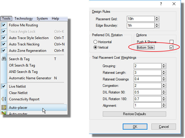
- Select the Auto-placer command on the Tools menu. Adjust the options as you see fit; in particular, note the Bottom Side option, which places the components on the underside of the board.
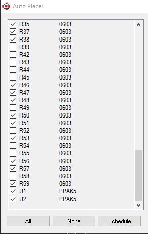
- Tick those components in the list which you wish to be placed automatically, and clear the tick against any you want to leave alone.
- Click OK.
- Once you have finished with the auto-placer, manually place any remaining components and start routing.
Groups and Placement Rooms
A group in terms of auto-placement is a set of components that you want to be placed next to each other. You assign the group to the component either on the schematic or in Design Explorer.
Assigning Group on Schematic
- Select the parts on the schematic.
- Invoke the Property Assignment Tool (the keyboard shortcut is A).
- Make up a group name and assign it to the property GROUP.
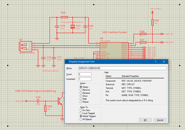
Making all selected parts part of the USBENGINE group with the Property Assignment Tool.
Individual components can be added to a group by editing the component properties and typing {GROUP=NAMEOFGROUP} into the Other Properties field. Curly brackets hide the property on the schematic.
Assigning Group in Design Explorer
- Launch Design Explorer from the main toolbar.
- Type a new group name beside a part to create a new group, or select from the combo box to add the part to an existing group, and press ENTER.
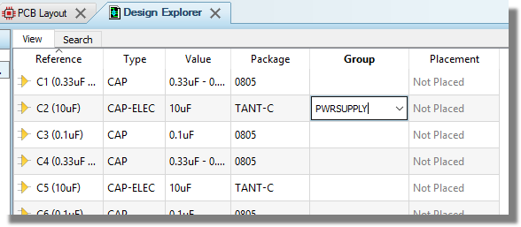
Assigning a CAP to the new PWRSUPPLY group by typing the group name in Design Explorer.
A component with no GROUP property is treated as though its group name were its part reference. A placement room named U1 will therefore capture the single component U1 without any GROUP property being assigned.
Placement Rooms
A placement room is a graphic object drawn on the layout that denotes an area for part placement. You can have multiple placement rooms and they can apply to either side of the board. This allows you to set out a floorplan on the PCB indicating where you want parts to be placed.
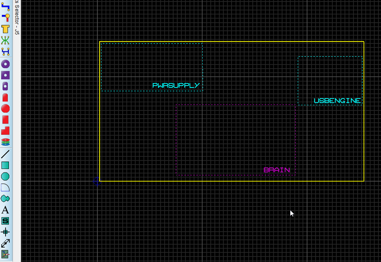
Laying out a floorplan with placement rooms assigned to groups
To lay out a placement room
- Select Room Mode on the mode toolbar (immediately below Connectivity Highlight Mode) and drag out a rectangle of the correct size and in the correct place.

- If a room is already placed, right click on the room border and select Edit from the resulting context menu.
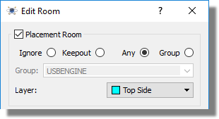
- Set the placement mode to Group, specify the group name and choose the side of the board for placement.
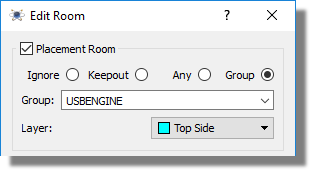
Click on the question mark on the dialogue form for more detailed help on the various options.
Placement Room Modes
The placement mode on the Edit Room dialogue determines how the auto-placer treats the room. Four settings are available:
- Ignore, the room has no effect on auto-placement at all. The placer will neither put parts inside it nor treat it as an obstacle.
- Keepout, the room is treated as an obstacle and no parts are placed inside it. This is a convenient way to keep components clear of a mounting hole, a connector cut-out or a heatsink area.
- Any, the room is available for placement and any component that has not been given a group may be placed inside it.
- Group, only components belonging to the named group are placed inside the room. The group is chosen from the Group combo box, which lists the group names found in the design.
The Layer setting decides which side of the board the room applies to: Top Side, Bottom Side or All. A room set to All is presented to the placer on both sides of the board, so a single room can host its group on the top and the bottom.
Placement rooms on the same layer may not overlap one another, and one room may not contain another. If they do, the auto-placer reports an error and stops without placing anything.
Placing Groups inside Placement Rooms
Having set up the groups and the floorplan you can run the auto-placer and it will put the correct parts in the correct room for you. Alternatively, you can select a group in the Object Selector and then right click and choose Place Group by Room to place every component in that group inside its room.
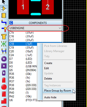
The Place Group by Room command on the Object Selector context menu
See Also: