DESIGN ROOMS
Introduction
There are often areas of circuitry on the PCB that require different clearances than the rest of the board. Sometimes we can cater for this by adding a design rule that applies to a specific layer on the board but in other cases what we need is to apply a design rule to a region of the board. In Proteus design rooms are the answer to this problem.
Normally, you place a design room by selecting the room tool and dragging out a box on the layout. You then use the Edit Room dialogue to specify the name of the room and which layers it covers. The layer coverage is set with two combos, From layer and To layer, so a room always occupies a contiguous range of layers rather than an arbitrary selection. Finally, you set up a design rule that applies to the named room and you can then enter custom clearances that apply in this area.
Design rooms can be an extremely useful tool in many different situations, from BGA escape areas to high power areas to high speed channels.
Placing a Design Room
To Place a Design Rule Room
1) Select the room icon and drag out the room on the PCB. When you are finished you will see the edit room dialogue form.
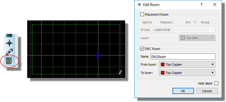
Placing a Room
You can also place a room using consecutive left clicks, much like the manual placement of a power plane. This will allow you to place polygonal design rule rooms (e.g. L shaped).
2) Switch to the DRC Room tab and specify the name for the room and which layers it occupies.
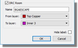
Naming and Defining the Room
Once the room is placed and named you can configure design rules and clearances for the room.
Setting Up Design Rules for a Room
To create a Design Rule for a Room
1) Having first placed the room on the board, open the design rule manager from the Technology menu. The room will appear in the region tree under each layer that it is present on.
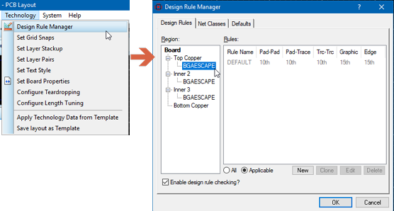
Opening the Design Rule Manager
Note that at first the rules that apply to the room region are inherited from a larger region. Inherited rules are drawn in a light grey to show that they are scoped to a larger region. In the picture above the rule that is in force is actually the board rule because neither a room rule nor a top copper layer rule has been created.
2) Click on the new button to create a new rule. From the resulting dialogue you need to scope the rule physically to the room region. You can also scope the rule electrically if required from the options at the bottom left. Finally, you set the required clearances.
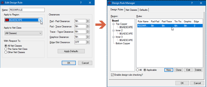
Defining a rule for the Room.
Design Rule Considerations
Before creating design rules for rooms it's important to have a grasp of the design rule hierarchy. This is discussed in detail in the topic linked below and summarised here in brief.
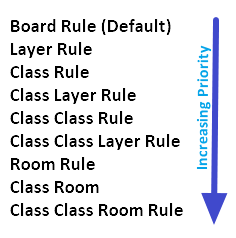
List of Design Rule Types in order of priority.
See Also:
You can see immediately that the room rule is a high priority rule and the other rules that apply in a room are higher priority still. This means that before you create a rule the clearances that will apply in the room area will be inherited from higher up the rule priority chain. Here's an example.
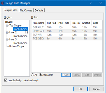
The Room inherits rules from larger regions when no rules are defined.
Inherited rules are drawn in a light grey whereas rules that are defined with a scope of the currently selected region are drawn in black. In the example above, any rule created with a scope of the BGAESCAPE room would therefore appear in black but layer rules and board rules will appear in light grey. So, in our example we have inherited:
- a Top Copper rule that applies to objects on the SIGNAL net class with respect to other objects on the SIGNAL net class.
- a Top Copper rule that applies to any objects belonging to the POWER net class.
- a board level rule that applies to any objects belonging to the HIGHPOWER net class.
- a board level rule that applies to anything else.
See Also:
Since we've create the design rule room to have different clearances we clearly want to make changes. There are two strategies and both are equally valid.
The Extreme Prejudice Approach
If we create a room rule that has no electrical filters then it will apply to all objects in the room. Since the room rule has higher priority than anything else and it applies to all objects it will nuke all of the inherited rules.
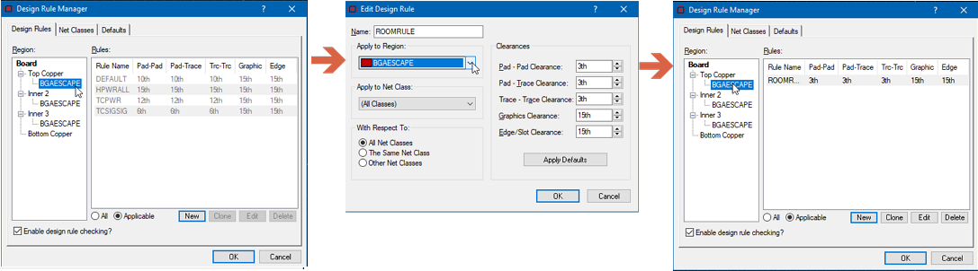
A room rule with no electrical filter will apply to all objects in the room and override all inherited rules.
This has the advantage of simplicity and can make things easier to understand. The downside is that if you do want to preserve some electrical rooms inside the room (e.g. the POWER clearances) you would have to set up a second rule (a CLASS ROOM rule) that used those clearances. The clone button is a relatively quick way to do this.
The Scalpel Approach
If we are only worried about certain connections then why throw away the rest of the rules framework ? Let's say for example that we want to give a bit more space to the SIGNAL net class inside the room. Here we could create a specific rule for the SIGNAL class in the room and everything else in the room would still use the inherited rules.
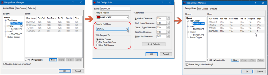
You can choose to create a room rule that applies only to certain signals. Other objects will then use inherited rules.
Which method you decide to use is largely a matter of personal preference but also depends on how much control you need over the objects inside the room. One benefit of starting with a room rule that applies to everything is that it really will apply to everything on the room, regardless of how many layers the room is on. Using a very specific rule in a multi-layer room can introduce subtleties because the rules that are inherited can differ on different layers of the room.
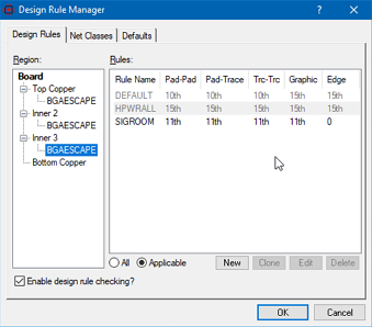
Rules in force on Inner 3 within the BGAESCAPE Room.
Notice in the screenshot above that we have one rule less applying on inner 3 within the room. This is because one of the rules was a layer rule and applied only to top copper (TCPWR). Of course, if the rules are defined with care from the outset this is probably exactly by design and not of concern. It is however something to be aware of and if you are concerned you might be better to take the 'start again' approach outlined above.
Via Style Override
In addition to design rule clearances, a DRC room can specify a via style override. This causes the router to substitute the room's nominated via style in place of the net class default whenever a via is dropped inside the room and the layer transition is compatible with the room's via style.
To configure a via style override, edit the room and select the desired via style from the Via Style dropdown on the DRC Room tab. If you wish to restrict the selection to micro-via styles only, check the Use Microvia checkbox first; this filters the dropdown to show only via styles that are flagged as micro-vias. The Use Microvia checkbox is only available when the board has an HDI stackup with micro-via drill spans; on non-HDI boards the checkbox is disabled. It is also cleared automatically when the room's placement mode is set to anything other than Ignore.
A via style override and the Exclude Foreign option are mutually exclusive. Ticking Exclude Foreign disables the Via Style, Use Microvia and Apply Style controls, and clears any values already set when the room is saved. If you need both behaviours over the same area, place two rooms.
The via style override is not a design rule and is not enforced by the DRC checker. It simply changes the default via style used during interactive routing when a via is placed inside the room. The user retains the ability to override it manually at any time.
Layer Range Compatibility
Because a micro-via can only span a single dielectric layer (e.g. Top Copper to Inner 1), the router must verify that the requested layer transition is compatible with the room's via style before applying the override. If the via being placed transitions between layers that do not correspond to a valid micro-via drill span in the board stackup, the room override is not applied and the net class default via style is used instead. Proteus displays a one-shot warning on the status bar when this occurs.
This check is performed automatically and ensures that the room's micro-via style is only applied where it is physically meaningful. The same principle applies to non-micro-via style overrides, although in practice these are less constrained since standard vias can span multiple layers.
Worked Example
Consider a 1+N+1 HDI board with the following stackup from top to bottom: Top Copper (TC), Inner 1 (I1), Inner 2 (I2), Bottom Copper (BC). The buildup layers are TC–I1 and I2–BC, so micro-vias can span TC↔I1 or I2↔BC only.
Suppose:
- Net class default: Via Style A (a standard through-hole via).
- DRC room override: Via Style B (a micro-via), with the Use Microvia checkbox enabled.
The user begins routing on the correct net class and the following via placements occur:
Scenario 1: Via outside the room (TC→I2)
The route transitions from Top Copper to Inner 2 outside the room. There is no room override in effect so Via Style A (the net class default) is used.
Scenario 2: Via inside the room, incompatible layer range (I2→TC)
The route enters the room and a via is dropped from Inner 2 to Top Copper. Although the via is inside the room, the layer transition I2→TC spans two dielectric layers and does not correspond to a valid micro-via drill span. The room's micro-via override is therefore not applied and Via Style A (the net class default) is used.
Scenario 3: Via inside the room, compatible layer range (TC→I1)
The user presses PGUP and PGDN to cycle through the valid layer destinations while routing and settles on Inner 1. Pressing SPACE places a via, and with smart vias enabled the best drill span for the transition is chosen automatically at the end. TC→I1 is a valid micro-via span (a single buildup dielectric), so the room's via style override now applies and Via Style B (the micro-via) is used.
This layer-aware behaviour means you can safely specify a micro-via override in a DRC room without worrying about it being incorrectly applied to incompatible layer transitions. The router handles the compatibility check automatically.
Apply Style
The Apply Style button on the Edit Room dialogue converts existing routed vias within the room to the room's nominated micro-via style. For each via inside the room, Proteus examines the connected trace layers to determine whether the via's drill span corresponds to a valid micro-via transition. If it does, the via's style is changed to the room's micro-via style. Vias whose layer transitions are incompatible with a micro-via span are left unchanged.
This is particularly useful after autorouting, since the autorouter uses only CNC drill spans and standard via styles. Once autorouting is complete, you can edit each micro-via DRC room and click Apply Style to convert the appropriate vias to micro-via styles in a single step.
Apply Style only operates on vias that are geometrically inside the room and whose drill span matches a laser (micro-via) span in the stackup. It does not move or re-route vias; it changes only the via pad style.
See Also:
Micro-Via Pad Styles and DRC Rooms
Exclude Foreign
A DRC room with the Exclude Foreign option enabled acts as an exclusion zone on its copper layers. Any copper inside the room boundary that is considered foreign is flagged as a DRC violation. Zone fills automatically punch a void matching the room boundary on the room's copper layers. You do not need to configure this separately.
The void is slightly larger than the room outline. It is inflated by half the zone's boundary thickness, so it is the physical copper edge of the plane that clears the room, not the centreline of the boundary track.
Determining What Is Foreign
When the room is not grouped with any component, all copper inside the boundary is foreign. Every pad, trace and zone fill on the room's layers will generate a DRC violation. This makes an ungrouped exclude foreign room equivalent to a total keep-out area on the specified layers.
When the room is grouped with one or more components, copper belonging to those components is exempt and will not generate violations. Specifically:
- Pads of grouped components are exempt.
- Traces routed to grouped component pads are exempt, even though traces themselves are not members of the group. The DRC checker determines this by object group membership, not by net: it walks up from the trace to the component that owns it and asks whether that component sits in the same group as the room. A trace that happens to share a net with a grouped component, but belongs to a component outside the group, is still foreign.
- All other copper (pads, traces or zone fills belonging to other components or nets) is foreign and will be flagged.
The typical workflow is to place the room, enable Exclude Foreign in the Edit Room dialogue, and then group the room with the component using the Group Objects command on the context menu. Once grouped, the component's copper is automatically exempted and the room enforces a void around it on the specified layers.
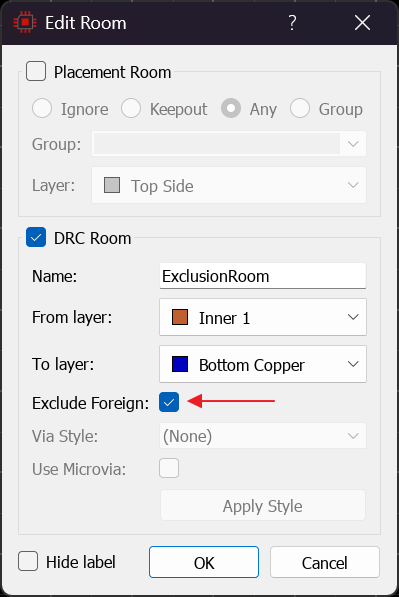
The Edit Room dialogue with the Exclude Foreign checkbox enabled on the DRC Room tab.
Typical Applications
- Magnetics and transformers where the datasheet specifies a copper void beneath the component to avoid eddy current losses or to meet safety isolation requirements.
- BGA components where the escape region requires tighter clearances or micro-via overrides. Note that Exclude Foreign and a via style override cannot be combined on one room: ticking Exclude Foreign disables the Via Style, Use Microvia and Apply Style controls, and clears them when the room is saved. Use one option or the other, or place two overlapping rooms, one carrying the exclusion and one carrying the via style override.
- Connectors with specific clearance envelopes defined by the manufacturer.
- Any component where the datasheet mandates a keep-out or restricted area on certain copper layers.
See Also:
Deleting a Room
To delete a room you need to both remove it from the layout and remove any configured rules in Design Rule Manager. Deleting on the layout is simply via the right click context menu on the graphic object. Similarly, you can simply select and delete rules from the Design Rule Manager. Note that if you've removed the room from the layout first you will need to switch the selection radio buttons in design rule manager from Applicable to All in order to see and remove the room related design rules.
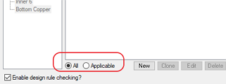
Switch to view All rules if you have deleted the room on the layout (since they are no longer applicable!).