BLOCK EDITING
Overview
Four block operations are provided: Copy, Move, Rotate and Delete and each operates on the currently tagged objects and the traces & vias within the tag box. If there is no tag box, then a default one is assumed comprising the total area occupied by the currently tagged objects. If there are no tagged objects, nothing at all will happen.
All block operations are group-aware. If any tagged object belongs to an object group, the selection automatically expands to include every member of that group before the operation is applied. This ensures that grouped objects always move, copy, rotate and delete as a complete unit.
Block Copy
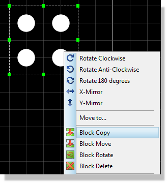
After creating a tag box as described in Tagging a Group of Objects, right clicking inside the tagbox and selecting the Block Copy command will cause a second box to appear over the tag box which you can then re position using the mouse. Clicking left will cause a copy to be made of the objects within the tag box whilst clicking right will abort the operation. Notably, the point at which you right click inside the tagbox defines the pickup point for the copy providing you with full control over the operation.
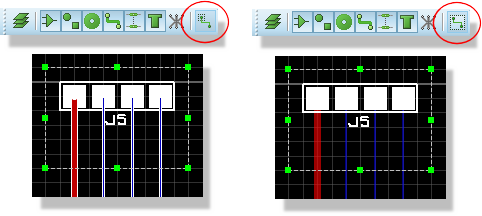
Control over what is tagged is handled via the selection filter. In particular, you can determine whether partial traces or only traces for which both ends of the trace are included in the tagbox are copied.
When copying grouped objects, the group hierarchy is duplicated alongside the objects. The copied group is fully independent of the original, preserving the same nesting structure with fresh internal identifiers.
Beware that copying components will generally leave the netlist management out of kilter as there will be multiple placements of the same component references. If, having routed a module that is to be repeated several times, your intention is to copy it out to save re-routing, you should turn off live netlisting, clear the netlist, perform the copy, sort the annotation to match and then sync up the layout. Note however that this is not a recommended process - It is much better and far safer to use Project clips which were designed for this purpose.
Introduction to Project Clips movie.
Block Move
After creating a tag box as described in Tagging a Group of Objects, left depressing the mouse inside the tagbox and dragging will pick up the block and move it. Again, the pickup point is the point inside the tagbox at which you depress the left mouse button. The mouse cursor will change to be the movement cursor to provide a visual indication when you can perform this operation.
Trace segments with one end only inside the tag box will be rubber banded.
Alternatively, you can right click inside the selected box and use the 'Move-To' command on the resulting context menu to programmatically position the block.
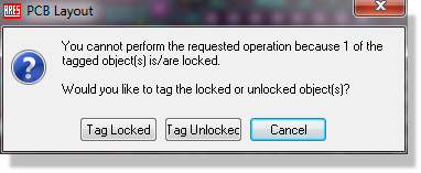
If you have one or more locked components/pads inside the tagbox you will be presented with a dialogue form allowing you to either select everything apart from the locked objects or to leave only the locked objects selected. The former will then allow you to move everything apart from locked objects while the latter will identify locked objects which you can then edit to unlock.
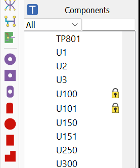
You can also see all locked components by entering selection mode and viewing the component list in the object selector (locked components have a padlock beside them)
Block Rotate
After creating a tag box as described in Tagging a Group of Objects, right clicking inside the tagbox and selecting the Block Rotate command presents you with the Block Rotate/Reflect dialogue form, allowing you to specify an any-angle rotation on the selected block.
The same form also carries Mirror X and Mirror Y checkboxes, so the block can be reflected about either axis instead of, or as well as, being rotated. Mirroring is group-aware in exactly the same way as rotation, so every member of a group is reflected together.
Control over what is tagged is handled via the selection filter. In particular, you can determine whether partial traces or only traces for which both ends of the trace are included in the tagbox are copied.
- Trace segments with one end only inside the tag box will be rubber banded although this generally leaves something of a mess it's best to rotate only completely enclosed sections of a layout.
- Rotation of whole groups of components to non-orthogonal angles (even 45 degrees) creates large numbers of off grid pads. Routing such boards can be very tricky, even with features such as real time snap and trace angle fixup.
- You can specify a rotation relative to one of four origin points, chosen from the Relative to list: Centre, Current Origin, Output Origin or Database Origin. Centre uses the centre of the selection and is typically what you want. Current Origin is the entry that picks up a false origin, which is useful for jobs such as aligning pads in a circle.
The autorouter will also perform poorly under such circumstances.
Block Delete
After creating a tag box as described in Tagging a Group of Objects, clicking on the delete button on the keyboard (or the Block Delete icon on the resulting context menu) will delete all tagged objects. Use the selection filter to control the object types and layers affected by the delete operation.
Remember that you can control which objects are selected in the tagbox by adjusting the selection filter, either before or after the tagbox has been created.
Align and Distribute
The align and distribute commands are designed to automate the neat spacing of like objects. They both work on the right click context menu from a block selection and also work with a discrete selection created by holding the CTRL key and left clicking consecutively on the parts.
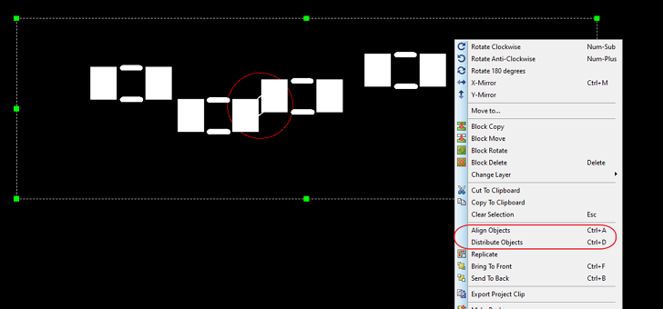
Roughly place parts and then use Align and Distribute to neatly handle the spacing.
Both dialogue forms are similar and allow you to align or distribute the selection. The Align form offers six actions: Align Left Edges, Align Right Edges, Align Top Edges, Align Bottom Edges, Centre Vertically and Centre Horizontally. The Distribute form offers four: Horizontal Spacing, Horizontal Centres, Vertical Spacing and Vertical Centres. The spacing actions equalise the gaps between neighbouring objects, whereas the centres actions equalise the distance between their centre lines. In typical usage you would align the parts and then distribute them.
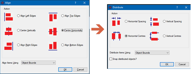
Align and then Distribute the components inside the selection.
Choosing the Reference Bounds
Both forms carry a selector, Align Items Using on one and Distribute Items Using on the other, that determines which part of each object the operation works from. Three options are available: Object Bounds uses the full extent of the object including its silkscreen and courtyard, Pad Bounds uses the outer extent of the copper pads only, and Pad Centres uses the pad centres. Pad Bounds and Pad Centres are the ones to reach for when you want the copper to line up, since the silkscreen extents of two different footprints rarely correspond.
Snap Distributed Objects
The Distribute form carries an additional checkbox, Snap distributed objects. With this checked, each object is moved to the nearest point on the current snap grid once the distribution has been calculated. This keeps the parts on grid, which helps subsequent routing, at the cost of a small error in the spacing.
The Align and Distribute keyboard shortcuts are very handy to learn and make this type of operation quick and easy. The commands can also be found on the Edit Menu in the layout module.
Replicate
Replicate makes a number of evenly spaced copies of the current selection in a single operation. It is available from the right click context menu of a block selection and from the Edit menu. Where Block Copy produces one copy that you then position with the mouse, Replicate produces as many copies as you ask for at a spacing that you type in, which makes it the right tool for arrays of LEDs, headers, mounting holes, test points and stitching vias.
Duplication
The Duplication group controls how many copies are made and where they are placed.
Offset and Separate
These two radio buttons decide how the step values are interpreted. Offset treats each step as a pitch, that is the distance from a point on one copy to the same point on the next. Separate treats each step as a gap, that is the clear space between the physical edges of one copy and the next. Separate is the mode to use when a mechanical drawing or a datasheet gives you a clearance rather than a pitch.
X-Step and Y-Step
The horizontal and vertical step between successive copies, interpreted as a pitch or as a gap according to the Offset and Separate setting above. Enter zero in one axis to build a single row or column.
No. of Copies
The number of copies to make, which does not count the original. Three copies of a single object therefore leave you with four objects on the board.
Relative to
Selects the feature of each object from which the separation is measured. Object Extremity uses the full extent of the object, Copper Extremity uses the outer edge of its copper alone, and Courtyard uses the courtyard boundary of a component footprint. The list adapts to what you have selected, so Courtyard is offered only when the selection contains component footprints. This selector is enabled only in Separate mode: in Offset mode the step is a pitch between identical points on successive copies, so no reference feature is needed.
Re-Annotation
When you replicate components you normally want each copy to take on its own component reference rather than duplicating the reference of the original, and the Re-Annotation group handles this.
Bind To
Selects the schematic part that the first copy binds to. Successive copies bind to the parts that follow it, so replicating D1 three times with Bind To set to D2 gives you D2, D3 and D4, each properly linked to its own schematic component. The parts must already exist in the schematic.
Increment
The step applied to the reference number for each successive copy. An increment of one produces a contiguous sequence, which is what you want in almost all cases; a larger increment is occasionally useful where the schematic numbering is not contiguous.
Radial Replicate
The radial variant of the command replicates around a circle rather than along a straight line. X-Step and Y-Step are replaced by an Angular Step in degrees and a Radial Offset/Separation, and a Radial Origin selector chooses the centre of rotation from Current Origin, Output Origin or Database Origin. Set a false origin at the centre of the circle and choose Current Origin to lay out a ring of pads, mounting holes or stitching vias.
Replicate operates on the objects you have actually selected. Unlike the block operations it does not expand the selection to take in the other members of an object group, so tag the whole group yourself if you want it replicated as a unit.
See Also: