Object Editing
Overview
Due to is its object oriented design, all objects on the layout are treated in much the same way and we can discuss generally their dragging, copying, movement, rotation, deletion and editing. You should note that traces and vias are not regarded as objects for this purpose; their editing is dealt with further under Route Placement and Editing. However, there are operations where traces attached to objects are affected by operations performed on the object - such cases are discussed here.
The Selection Filter
Board design by it’s very nature consists of several layers (silkscreen, copper layers, edge layer, mechanical layers etc.). Despite this, Proteus provides a modeless selection mechanism where the object under the mouse is identified regardless of whether it is on the current layer. This works extremely smoothly in most cases but the selection filter provides the means by which you can override the default behaviour in a given situation.
The selection filter can be found at the bottom left of the layout application window

Selection Filter
The purpose of the selection filter is simply to determine which object types are considered ‘hot’ in any given mode. Additionally, the icon directly to the right of the layer selector determines whether all layers or only the current layer are considered to be ‘hot’. By toggling these icons you can therefore have complete control over both which objects and which layers are hot at any given time.
When the mouse is over a ‘hot’ object a visual cue will be given to light dashed line will appear to provide instant feedback telling you what exactly the mouse is considered to be pointing at.
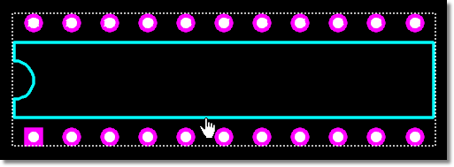
When the mouse is over a 'hot' object it becomes highlighted
Sophisticated algorithms are in place to cater for the cases where, for example, two tracks on different layers are placed in parallel. Whilst the obvious solution is to look for a point on the desired track which is visible on it’s own, the behaviour in such a case is prejudiced by the layer currently selected in the Layer Selector. You could therefore switch the layer selector onto the layer of the trace you want to select and then click on the track.
It is extremely important to realise that this object ‘twitching’ indicates only the object that will be acted upon when you click the mouse. It does not indicate what the action will be (selection, placement, etc.). Indication of action is provided by the mouse cursor and is summarised below :
| Cursor | Description |
|
|
Standard Cursor |
|
|
Placement Cursor - Left click will place an object according to the current mode |
|
|
Selection Cursor - Left click will select the current object under the mouse |
|
|
Movement Cursor - Left click will move the current object(s) selected |


Using these two visual indicators together provides an extremely intuitive method for both knowing what object the mouse is over and also what action will be performed when you left click the mouse on that object.
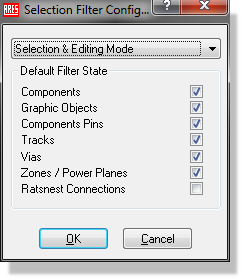
Finally, while considerable time has been given to choosing a sensible default selection set for each mode in the layout module you can override it if you decide that you prefer to operate in a different way. Default selection filters on a per mode basis can be configured via the Set Selection Filter command on the System menu.
See Also:
The Selection Filter (Tutorial)
Tagging a Single Object
Provided the object is considered ‘hot’ (as defined via the selection filter)any object may be tagged by pointing at it and clicking right. This action highlights the object and presents a context menu containing relevant actions for that object.
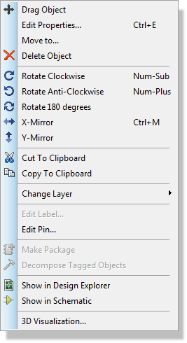
Right click to reveal the Context menu
Alternatively, where an object is ‘hot’ and the mouse cursor indicates selection (pointed hand) a left click on the object will select the object
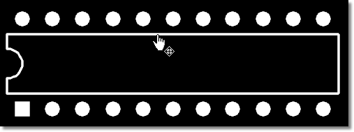
A useful trick for precision movement of a part is to map the ‘Drag Object’ command on to a keyboard shortcut. You can then tag the part, invoke the keyboard shortcut and use the keyboard arrow keys to move the part by a single grid setting.
Tagging a Group of Objects
The normal way to tag a group of objects is by dragging a box around them using the right mouse button. Once the tag box is created, the enclosed space can be refined by dragging the green ‘handles’ as required. The ‘trace bounds’ selection icon can be used to determine whether only fully enclosed traces or partially enclosed traces are tagged.
After placement of the tagbox the selection filter can be used to refine which objects are tagged, providing a live update according to the current configuration. See Block Editing Commands for more information.
Only one tag box can exist at any one time - drawing a new one will delete the old one, and untag the objects within it.
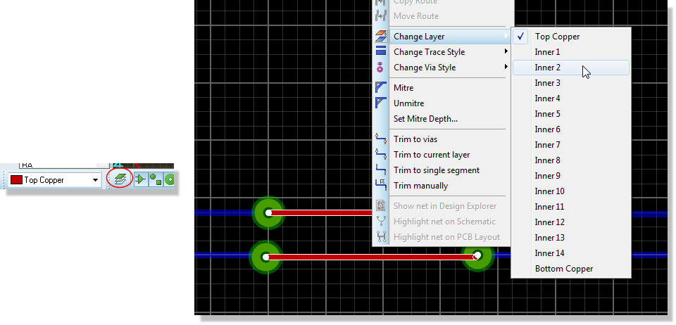
There are a few operations - notably trace editing - where you can create a selection of tagged objects using the mouse. To do this, first switch to selection mode and then CTRL+left click on each track individually. When you are finished, right click on any one of the tracks to change their width, layer or via style.
Untagging All Objects
To untag all the objects, you need simply to point where there is no object and click left. This will also remove the tag box if one has been defined.
Performing an explicit Redraw Display command will also untag all objects, which can be handy if the board is very densely packed and there is nowhere free of objects on the screen. Redraw Display has no default keyboard shortcut, so map one to it from the keyboard configuration dialogue if you expect to use it often.
Creating Object Groups
Object groups allow you to create persistent logical collections of objects that behave as a unit during editing operations. Unlike a tag box selection which is temporary, an object group is saved with the design and remains in effect until you explicitly ungroup the objects.
Object groups for editing are distinct from autoplacement groups, which are defined by the GROUP property on components and used by the autoplacer to keep related components together. The two features are independent of each other.
Why Use Object Groups
Object groups serve two main purposes on the PCB layout:
- Repositioning related objects together. If several objects are positioned relative to each other (for example, a connector with associated mounting holes and keep-out graphics) you can group them so that they always move, rotate and mirror as a single unit. This prevents accidental misalignment when adjusting the layout.
- Binding a DRC room to a component. When a component datasheet specifies clearance or exclusion requirements, you can place a DRC room around the component and group the two together. This is particularly useful with exclude foreign rooms, where copper not belonging to the grouped component is flagged as a DRC violation. Typical applications include void areas beneath magnetics, BGA escape regions with tighter clearances or micro-via overrides, and connectors with specific clearance envelopes.
What Can Be Grouped
Almost all objects in the object database can be grouped: components, packages, 2D graphics, dimensions, zones, pads and rooms. Traces and vias belong to the route database and cannot be members of a group. However, when you perform a block operation on grouped objects, any traces bounded by the selection will still be affected according to the normal selection filter rules.
DRC violation flags and script objects cannot be grouped. If either is present in the selection it is silently dropped when the group is formed.
Creating a Group
To create a group, tag the objects you wish to group using a tag box or by CTRL+clicking individual objects, then right click and select Group Objects from the context menu, or use the Group Objects command on the Edit menu. A confirmation message will appear in the status bar showing the group and its members.
Nested Groups
Groups can be nested to form a hierarchy. If all the objects you select already belong to the same group, the Group Objects command will create a sub-group within that parent group. This allows you to organise complex arrangements into logical tiers; for example, a power supply section might contain sub-groups for the input filter, the regulator stage and the output capacitors.
If instead your selection spans several different groups, or mixes grouped and ungrouped objects, the command merges everything into one new group rather than nesting. In doing so it deliberately pulls in the members of any partially selected group that you did not select, so that no object is left orphaned from the group it belonged to. This is worth bearing in mind when you drag a tag box across an area that already contains groups: the resulting group can be larger than the selection you drew.
Use the confirmation message in the status bar to check the membership of the group you have just created. If it lists more objects than you expected, the merge branch described above has taken effect and you may want to ungroup and start again.
Selecting and Working with Groups
When you interact with any member of a group, the selection automatically expands to include all members of that group. This applies to both single-object operations (dragging, context menu commands) and block operations on a tag box selection. If the group contains nested sub-groups, these are included as well; the expansion always operates from the root of the group tree.
The following table summarises which operations are group-aware:
| Operation | Group Behaviour |
| Drag | Dragging any group member moves the entire group. Traces attached to group members are rubber-banded as normal. If you click without moving, the group expansion is cancelled and the Edit Properties dialogue opens for the clicked object. |
| Delete | Deleting any group member via the context menu deletes the entire group. |
| Rotate and Mirror | Rotate or mirror commands from the context menu transform the entire group about the clicked object. |
| Move To | The Move To context menu command moves the entire group by the specified offset. |
| Block Move | All group members move together. Traces bounded by the selection are also affected according to the selection filter. |
| Block Copy | All group members are copied. The group hierarchy is duplicated with fresh identifiers so the copy is independent of the original. |
| Block Rotate | All group members rotate together about the specified origin. |
| Block Delete | All group members are deleted together. |
| Align | All group members are included in the alignment operation. |
| Clipboard and Project Clips | Group structure is preserved through cut, copy, paste and project clip export/import. |
Edit Properties always operates on the individual object regardless of group membership. You can edit a component's properties without affecting the rest of the group.
Distribute, Replicate and Change Layer operate on individually selected objects and do not expand the selection to include other group members.
Ungrouping
To ungroup, tag any member of the group, right click and select Ungroup Objects from the context menu, or use the Ungroup Objects command on the Edit menu. This dissolves the entire group hierarchy from the root down, returning all member objects to an ungrouped state.
Groups and the Clipboard
Group structure is preserved when objects are copied via block copy, cut to the clipboard or saved as project clips. When the objects are pasted, the group hierarchy is recreated with fresh internal identifiers so that the pasted group is independent of the original.
See Also:
Deleting an Object
Any tagged object can be deleted by pointing at it, clicking right and selecting Delete Object from the resulting context menu. Any traces connected to its pads will remain in place, allowing a different pad or package to be placed over them.
The Delete Object command operates on a single object only. When multiple objects are selected, use Block Delete instead. Note also that if the object belongs to a group then deleting it deletes every member of that group, since the delete operation treats the group as a single unit. Ungroup the objects first if you need to delete only one of them.
An important and rather subtle distinction exists when you are removing a footprint that has been placed on the board; you can either delete the package directly in the layout module or you can delete the associated component on the schematic.
- If you delete the package directly in the layout any placed tracks that connected to the package will remain.
- If you delete the component on the schematic then, when you click on changes pending on the layout, both the footprint and the tracks connecting to it will be removed
Dragging an Object
You can drag (i.e. re position) any tagged object by pointing at it and then dragging the mouse with the left button depressed.
Any traces attached to the object will be rubber banded (stretched) unless both ends connect to it, in which case the route will be moved wholesale.
You can also programmatically move a footprint by using the 'Move to' command on the right click context menu.
Editing an Object
Some objects, especially packages, components and graphics text have properties that can be edited with a dialogue form. There are two ways to do this:
- A tagged object can be edited by pointing at it and then clicking left as if to drag it but without moving it.
- You can right click on an object and select Edit Properties from the resulting dialogue form.
Locking an Object
You can lock components, packages or single pads on the layout such that they cannot be moved, rotated or deleted. This is useful if, for example, you have connectors or mounting holes that need to be in a specific position on the board and you wish to ensure that they are not inadvertently moved.
To lock an object on the PCB
- Place the object on the layout in the specified position.
- Edit the object by right clicking to highlight and then selecting Edit Properties from the context menu to launch the resulting dialogue form. Note that for components you must click on the component outline: if you click on a component pad you will get the Edit Pad dialogue form instead.
- Check the box at the bottom of the dialogue as shown below to lock the object. Note that only the object types specified above can be locked
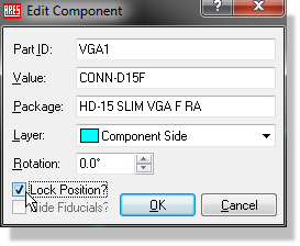
The Lock Position check box
While no visible indication of a locked object is provided on the layout (to avoid clutter) you can find all the locked objects on the board as follows :
To find all locked objects on the PCB
- Switch to selection mode. Locked objects have a padlock beside them.
- Double click on a locked component to select it and navigate to it on the layout.
OR
- Tag the entire board (right click and drag a box) and then attempt a block operation.
- From the resulting dialogue box select the option to tag only the locked objects on the board.
Highlighting a Component by Name
When Selection Mode is selected, the Object Selector lists all the components in the design. Clicking on the selector toggle tags the selected component causing it to be highlighted, and zooms in to display it in the centre of the screen.
Alternatively, you can locate a component using the Goto Component command on the View menu (CTRL+C).